section in PDF
manual in PDF


|
|
|
| |
| Get this section in PDF |
Get entire manual in PDF |
|
Chapter 13: IXIA 250 Chassis
This chapter provides details about Ixia 250 chassis—its specifications and features.
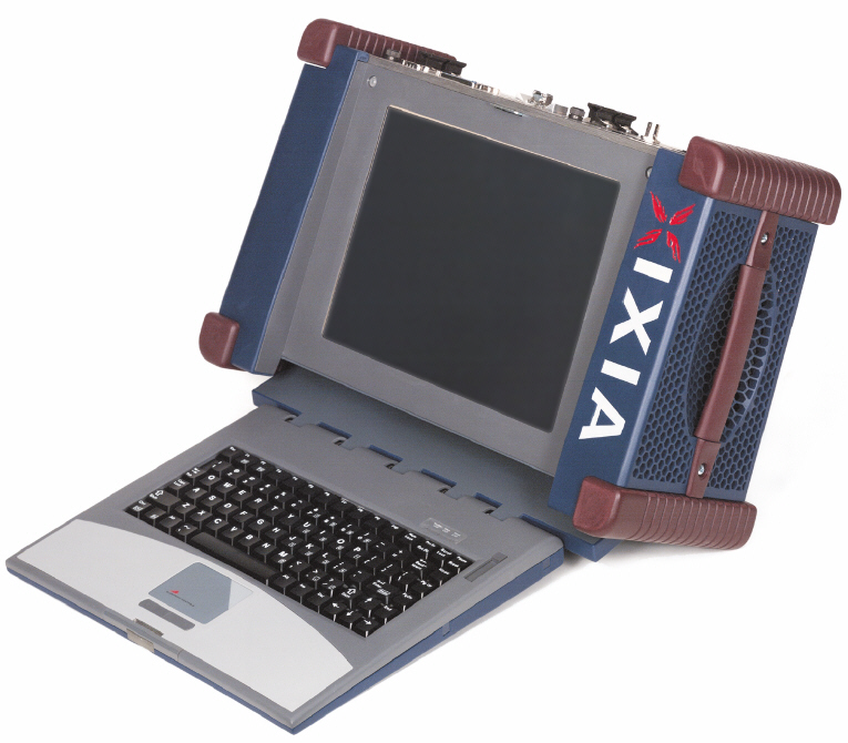
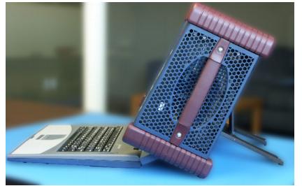
The IXIA 250 is a Field Service Unit (FSU) chassis with a built-in 10/100/1000 port and an additional two slots for Ixia Load Modules, which may be high-
powered modules. The IXIA 250 is shown in the following figure.
Figure 13-1.
IXIA 250 Chassis
Operation
Setup
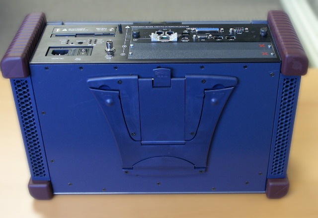
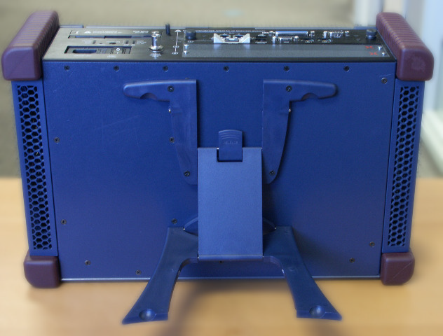
The IXIA 250 incorporates an adjustable support, shown collapsed in Figure 13-2 and extended in Figure 13-3.
Figure 13-2. IXIA 250 Integrated Support (Collapsed)
Figure 13-3. IXIA 250 Integrated Support (Extended)
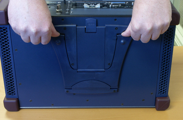
The support is extended by placing your thumbs at the upper left and right corners of the cutouts and pushing down as shown in Figure 13-4. Ensure that the stand is stable in one of its available locking positions.
Figure 13-4. IXIA 250 Integrated Support Operation
The keyboard is released by pressing on the button at the top of the chassis, as shown in Figure 13-5.
Figure 13-5. IXIA 250 Keyboard Release
Unfold the keyboard and press down on the hinge until it lies flat.
Figure 13-6. IXIA 250 Keyboard
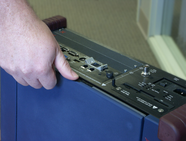
Power is applied to the unit by plugging it in and toggling the `1/0' switch as shown in the following figure.
Figure 13-7. IXIA 250 Power
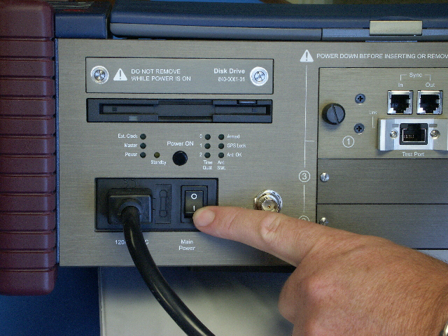
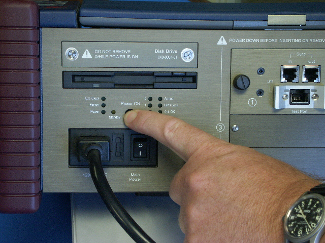
This applies power to the chassis, but does not turn on the computer within. The separate Standby switch must be pressed, as shown in Figure 13-8. This may also be used to put the computer into standby mode at a later time. Should the IXIA 250 experience a power failure, it does not automatically start the operating system.
Figure 13-8. IXIA 250 Standby Switch
Computer Operation
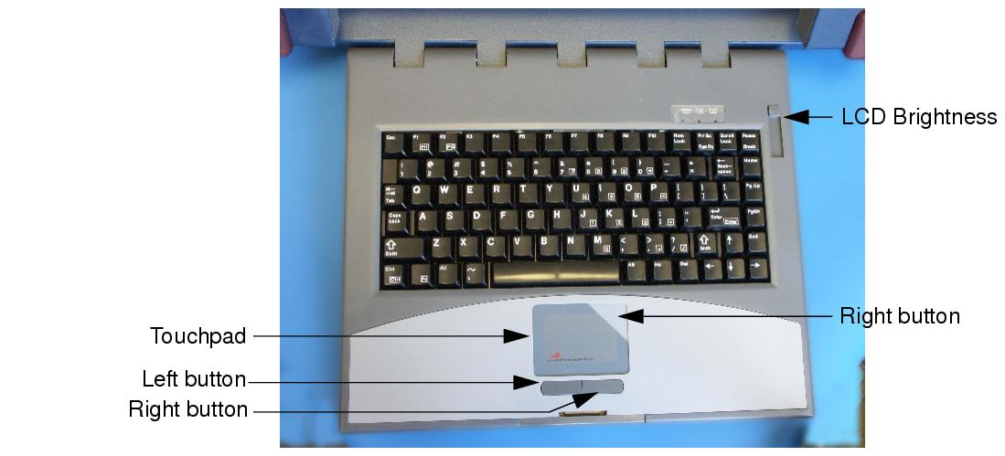
The computer on the IXIA 250 is operated as any other computer system running Windows 2000 Server. The keyboard is used for all typed input. The touchpad at the bottom of the keyboard, as shown in the following figure, is used to position the cursor and click the left and right mouse buttons.
Figure 13-9. IXIA 250 Keyboard and Touchpad
Move around the touchpad, following the cursor on the screen. Use the buttons under the touchpad as you would use the left and right mouse buttons on a mouse. Double tapping on the touchpad is equivalent to a double-mouse click. Pressing in the shaded area at the top-right of the touchpad is equivalent to a right mouse button click.
The intensity of the LCD screen is controlled by the slide switch at the upper right corner of the keyboard.
In addition to the use of the touchpad, an external mouse may be connected to the Keyboard/Mouse port at the back of the chassis. Furthermore, the LCD screen is touch sensitive and may be used as an alternative to the touchpad or mouse. Touching the screen is equivalent to pressing and holding the left mouse button at that point and taking your finger off the screen is equivalent to releasing the mouse button.
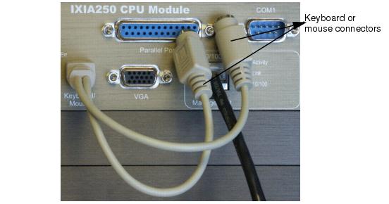
An external keyboard may be attached to the Keyboard/Mouse port at the back of the chassis. When both an external mouse and keyboard are required, they may be attached with the use of the supplied `Y' adapter, as shown in Figure 13-10. Attach the keyboard and mouse to either connector.
Figure 13-10. IXIA 250 Keyboard/Mouse `Y' Adapter
The rear panel of the IXIA 250 contains additional connectors for external devices. This is shown in Figure 13-12 and further explained in Table 13-1.
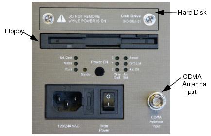
A floppy drive and access to the hard disk is provided on the left rear of the chassis, as shown in the following figure.
Figure 13-11. IXIA 250 Floppy and Hard Drive Access
Test Operation
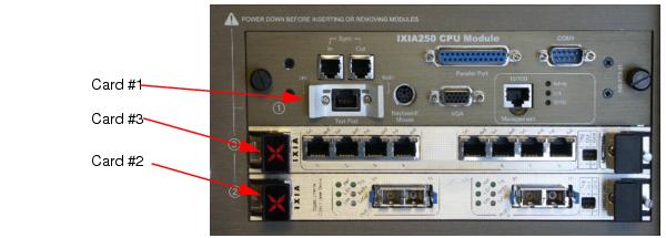
Device testing may be accomplished using the built-in port or by plugging in additional Ixia load modules. The following figure shows two additional boards in an IXIA 250 chassis.
Figure 13-12. IXIA 250 with Additional Load Modules
The IXIA 250 accepts any two single-wide or one double-wide load modules. See the remaining chapters of this manual for a discussion of available load modules. When using Ixia software to access the load modules, the cards are numbered as shown in Figure 13-12. That is, the built-in port is card number 1, the lower card in the chassis is card number 2, and the card above that is card number 3.
When the IXIA 250 is ordered with the Gigabit-only option, then one of two optional connectors may be attached to the Test Port. The connectors are either copper (RJ-45) or fibre optic SFP module. The module to which the connector is attached is hot-swappable. Merely press the release tabs on either side of the connector and pull out the connector.
Sync-in/Sync-out connectors are provided to daisy chain the IXIA 250 with other chassis.
When the CDMA option is installed, an appropriate antenna should be attached to the rear panel, as shown in Figure 13-11. Refer to Ixia 100 Chassis for a full discussion of the use of the CDMA feature. LEDs are provided to indicate the status of the CDMA time lock; the aforementioned chapter has a discussion of their interpretation.
Specifications
Ixia 250 Chassis
Ixia 250 computer and chassis specifications are contained in Table 13-2.
Test System
The test system specifications are contained in Table 13-3 on page 13-13.
|
|
Did this document answer your question?
If not, let us know! |
|