section in PDF
manual in PDF


|
|
|
| |
| Get this section in PDF |
Get entire manual in PDF |
|
Chapter 34: IXIA Xcellon-Flex Load Modules
This chapter provides details about Xcellon-Flex family of load modules—specifications and features.
The Xcellon-Flex family of high speed load modules delivers high-density, high-performance test solutions. Xcellon, the architecture behind these load modules, features aggregation of multi-core CPUs and high memory to meet testing needs for high-scale performance.
The Xcellon-Flex family consists of the following load modules:
The card names are FlexAP10G16S, FlexFE10G16S, FlexAP1040SQ, and FlexFE40QP.
The Accelerated Performance load module provides architecture for layer 2-7 performance testing, providing ultra-high-scale session and protocol emulation per port. The Full Emulation load module is for layer 2-3 mid-range protocol emulation and scale capacity testing for switches and routers. The Xcellon-Flex Combo 10/40GE Accelerated Performance load module provides both 10GE SFP+ and/or 40GE QSFP+ ports in a single chassis slot. It uses aggregation technology to combine CPU power and memory, and provides ultra-high networking protocol scalability. The 4x40GE Full Emulation load module has a rich layer 2-7 feature set and is well suited for mid-range protocol emulation and scale testing. The load module is ideal for manufacturers of large-port-count, converged data center switches.
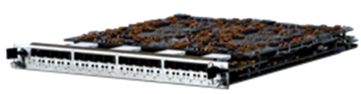
The Xcellon-Flex family load module is shown in the following figure:
Figure 34-1. Xcellon-Flex Module-FlexAP10G16S
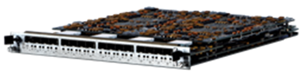
The Xcellon-Flex family load module is shown in the following figure:
Figure 34-2. Xcellon-Flex Module-FlexFE10G16S
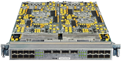
Figure 34-3. Xcellon-Flex Module-FlexAP1040SQ
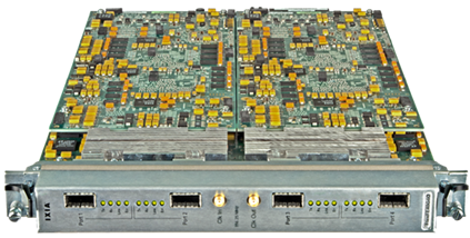
Figure 34-4. Xcellon-Flex Module-FlexFE40QP
Part Numbers
The part numbers are shown in Table 34-1.
Specifications
The load module specifications are contained in Table 34-2.
Table 34-2.
Mechanical Specification of FlexAP10G16S/FlexFE10G16S Load Modules
Front Panel
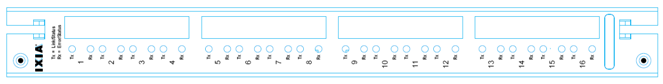
The Front panel of FlexAP10G16S/FlexFE10G16S load module is shown in the following figure:
Figure 34-5. Front panel of FlexAP10G16S/FlexFE10G16S
Led Panel
Table 34-3. Led panel of FlexAP10G16S/FlexFE10G16S Load Module SpecificationsWhen port is in aggregation mode (the PCPU resource is used by other port), TX/RX LEDs are inactive (i.e. off). The aggregation egress port will have normal TX/RX LED operation.
Mechanical Specification of FlexAP1040SQ Load Modules
Front Panel Production – 944-1062-02
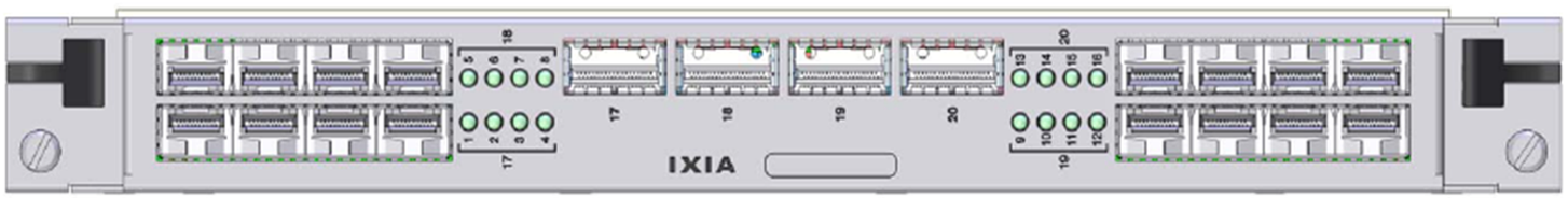
The Front panel of FlexAP1040SQ load module is shown in the following figure:
Figure 34-6. Front panel of FlexAP1040SQ
Led Panel Production – 944-1062-02
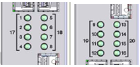
The Led panel of FlexAP1040SQ load module is shown in the following figure:
Figure 34-7. Led panel of FlexAP1040SQ
Table 34-4. Led panel of FlexAP1040SQ Load Module SpecificationsWhen port is in aggregation mode (the PCPU resource is used by other port), TX/RX LEDs are inactive (i.e. off). The aggregation egress port will have normal TX/RX LED operation.
Definition matches the 40G Only definition.
Mechanical Specification of FlexAP40QP4 Load Modules
Front Panel
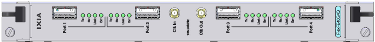
The Front panel of FlexAP40QP4 load module is shown in the following figure:
Figure 34-8. Front panel of FlexAP40QP4
Led Panel
Table 34-5. Led panel of FlexAP40QP4 Load Module Specifications
|
|
Did this document answer your question?
If not, let us know! |
|