section in PDF
manual in PDF


|
|
|
| |
| Get this section in PDF |
Get entire manual in PDF |
|
Appendix A: XAUI Connector Specifications
Description
The following cable and accessories for the 10GE XAUI cards are described in this appendix. These include the following:
- Standard Connector Specifications: The signals carried on the Load Module's XAUI connector.
- Front Panel Loopback Connector: A connector used to loopback XAUI signals at the external connector.
- Standard Cable Specification: The CAB10GE500S1 (20") and CAB10GE500S2 (40") cables.
- SMA Break-Out Box: The BOB10GE500 SMA break-out box.
- XAUI Fujitsu to XENPAK Adapter: An adapter used with Ixia XENPAK load modules to create a XAUI interface.
- XAUI Tyco Interoperability Backplane HM-Zd Adapter: An adapter used to connect to the Tyco Interoperability Backplane.
Standard Connector Specifications
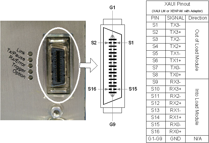
The Ixia XAUI Load Module's front panel connector is the Fujitsu MicroGiGa. This connector can be mounted on the Device Under Test (DUT), eliminating the need for SMA cables. This part is also available directly from Fujitsu as part number FCN-268D008-G/1D-/2D.
The connector as mounted on the Ixia load module is shown in Figure A-1, along with the signal names, functional description, and connector pin assignments. The same pinouts apply to XENPAK load modules which use the XENPAK to XAUI adapter.
Figure A-1. Fujitsu MicroGiGa Connector Mounted on Load Module
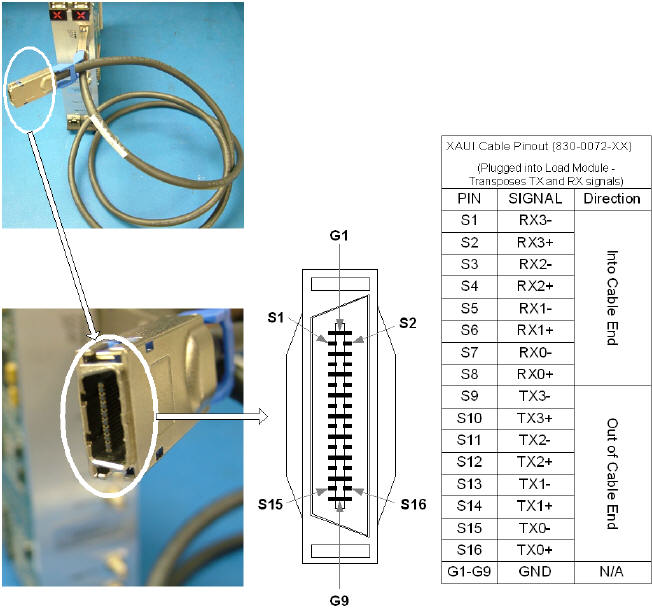
The XAUI Cable plugs into the load module and transposes the transmit and receive signals, as shown in the following figure.
Figure A-2. XAUI Cable Pinouts
Front Panel Loopback Connector
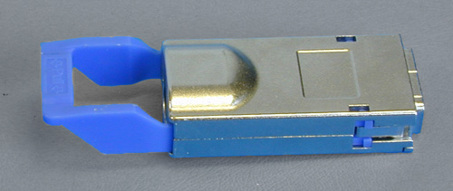
In order to verify that the Ixia XAUI Load Module is operational, a loopback connector may be used to test external loopback on the front panel. You can remove the connector by pulling back on the blue handle, releasing the connection to the Fujitsu MicroGiGa connector. The loopback connector (Ixia P/N LPG10GE500) is shown in the following figure.
Figure A-3. XAUI Front Panel Loopback Connector
Standard Cable Specification
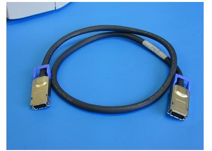
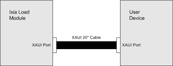
The same connector and pin assignments used on the Load Module can also be used on the Device Under Test (DUT). Ixia supplies a 20-inch cross-pinned cable assembly (CAB10GE500S1) that allows a straight connection as shown in Figure A-5. This cable can also be used for loopback testing on an Ixia chassis equipped with two or more XAUI ports. Longer cable assemblies can be made on request, but we do not recommend that the cable length exceed 2 meters, because losses and skew may become unacceptable. Ixia makes a 40" cable available as part number CAB10GE500S2. The 40" cable is shown in Figure A-4.
Figure A-4. Ixia XAUI Cable (CAB10GE500S2)
Figure A-5. Direct XAUI Interface Using Ixia Supplied Cable
SMA Break-Out Box
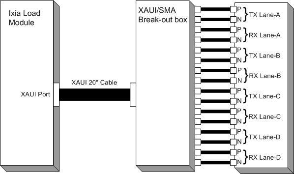
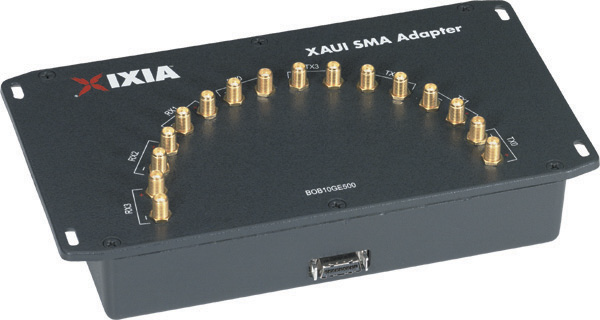
If the DUT uses coaxial connectors for the XAUI interface, a special break-out box (BOB10GE500) is required in addition to the XAUI cable, as shown in Figure A-6. You must provide the sixteen 50 ohm coaxial cables with a male SMA connector on the end that mates to the BOB. The actual break-out box is shown in Figure A-6.
Figure A-6. XAUI SMA Break-Out Box
Figure A-7. XAUI SMA Break-Out Box
When using coaxial cables for the XAUI interface, extreme care should be taken to match the electrical lengths of the two cables in each pair. The pairs can be of different lengths, since the XAUI SerDes should automatically correct for skew between lanes. Skew between the `P' and `N' lines within a pair, however, can introduce bit errors. The XAUI edge-rates can be as short as 60ps. Therefore, the total in-pair skew should be kept below 30 ps to avoid bit-errors. Some of this in-pair skew must be budgeted to the Load Module, Ixia XAUI cable, BOB, and the DUT. Allocating 10ps of in-pair skew to the coax cables would require length matching them to within about 0.08" (for RG-174). The propagation velocity of coax can vary slightly between manufacturers, lots, and as it is bent or stretched. Therefore, we recommend that coax cables be kept as short as possible.
XAUI Fujitsu to XENPAK Adapter
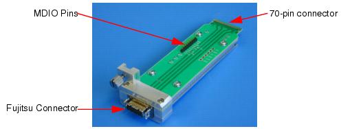
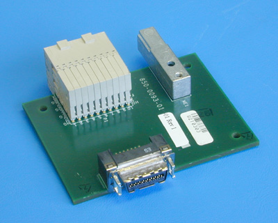
The electrical interface to XENPAK is XAUI, which uses an industry standard 70-pin connector. Ixia's XAUI Load Module, however, uses a Fujitsu MicroGiGa connector to both transmit and receive four XAUI lanes through eight twisted pairs through a 20" cable. Ixia offers an adapter (part number FXN10GE500) that routes the XAUI lanes from the Fujitsu connector to the pins on the XENPAK connector.
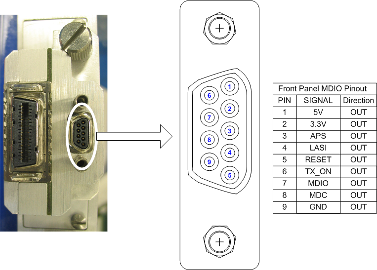
This enables a XENPAK Load Module to act as a XAUI Load Module. However, the XENPAK Load Module can only run in Ethernet mode and transmit and verify Layer 2 or 3 traffic. Furthermore, there is an FD D-sub connector for MDIO on the front panel of the XENPAK Load Module (shown in Figure A-9 on page A-9). Both the MDIO and power are available through pins on the adapter and serve the same function as the D-sub connector on the XAUI Load Module.
The adapter is shown in Figure A-8.
Figure A-8. Fujitsu to XENPAK Adapter
Figure A-9. CX4 and XAUI MDIO Pinouts
XAUI Tyco Interoperability Backplane HM-Zd Adapter
XAUI interoperability testing has been conducted using a Tyco built simulated backplane. Each XAUI vendor has been required to build a line card to connect to the backplane through the Tyco HM-Zd connector. Tyco had also built an SMA adapter to connect to the backplane, but it is too time-consuming and difficult to connect through SMAs. Ixia has built an HM-Zd adapter (P/N FTY10GE500), which allows direct connection to the backplane through the Fujitsu connector, saving significant setup time. This is shown in Figure A-10.
Figure A-10. Tyco Interoperability Backplane HM-Zd Adapter
|
|
Did this document answer your question?
If not, let us know! |
|