section in PDF
manual in PDF


|
|
|
| |
| Get this section in PDF |
Get entire manual in PDF |
|
Chapter 4: Optixia XM12 Chassis
This chapter provides details about the Optixia XM12 chassis—its specifications and features.
The Optixia XM12 is a next generation chassis that is a combination of the Optixia backplane architecture and a XM form factor. The 12-slot platform allows for higher port density load modules. The XM12 High Performance version has two 2.0 kW powersupplies, while the Standard version has two 1.6 kW power supplies. An upgrade kit is available to convert the Standard XM12 to the High Performance version. See High Performance Upgrade Kit on page 4-18.
The Optixia XM12 Chassis has 12 slots for support of up to 12 single wide load modules. The Optixia XM12 supports all load modules with improved system power and cooling. The Optixia XM12, shown in Figure 4-1, was specifically designed to allow the hot-swapping of modules, without requiring the chassis to be powered down.
Figure 4-1. Optixia XM12 Chassis
The Optixia family of chassis has improved data throughput between Load Modules and the chassis, with improved backplane performance.
The Optixia chassis provides improved modularity of major components to reduce downtime of a failed chassis and reduce the probability of needing to remove a failed chassis from the test environment. Among the modular features provided are:
The motherboard and power supplies are accessible from the front of the chassis. Each of the modular components is capable of being removed in the field and replaced with minimum downtime for the customer.
Specifications
XM12 Chassis
The Optixia XM12 computer and chassis specifications are contained in
Table 4-1.Electrical Grounding requirements for Multi-Chassis system configuration
To ensure consistent grounding:
If equipment grounding is not consistent, the software will detect this and shutdown to protect equipment from damage.
LEDs/LCD Display
The Optixia XM12 has the following set of front panel LEDs, for each load module slot:
LCD Display
An LCD display is provided on the chassis to indicate the status of the chassis without an external display device (monitor). The LCD operates in two modes:
Supported Modules
The modules that are supported on the Optixia XM12 are listed in Table 4-3..
HSE100GETSP1-01
HSE40/100GETSP1-01
LSM1000XMVDC8-01
LSM1000XMVDC12-01
LSM1000XMVDC16-01LSM1000XMVDC16NG
LSM10GXM2GBT-01
LSM10GXM2S-01
Includes 10GBASE-T version and SFP+ version.
LSM10GXMR2GBT-01
LSM10GXMR2S-01
Includes 10GBASE-T version and SFP+ version.
LSM10GXM4GBT-01
LSM10GXM4S-01
Includes 10GBASE-T version and SFP+ version.
LSM10GXMR4GBT-01
LSM10GXMR4S-01
Includes 10GBASE-T version and SFP+ version.
LSM10GXM8GBT-01
LSM10GXM8S-01
Includes 10GBASE-T version and SFP+ version.
LSM10GXMR8GBT-01
LSM10GXMR8S-01
Includes 10GBASE-T version and SFP+ version.
NGY-NP4-01
NGY-NP2-01
-256 version has 256MB of processor memory per portHot-Swap Procedure
Each Optixia XM12 chassis provides the ability of removing and reinstalling a Load Module without requiring the removal of power from the rest of the chassis. The process of removing/installing a Load Module does not impact either the operation of the OS or load modules installed in the chassis.
The hot-swap procedure is detailed in Appendix D, Hot-Swap Procedure.
SFF Adapter Module
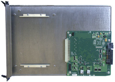
The Optixia XM12 adapter module allows legacy modules to be fit into the XM12 chassis. Figure 4-2 on page 4-12 shows an SFF adapter module.
Figure 4-2. SFF Adapter
A legacy module is inserted into the front of the adapter module and connects to the pins in the rear of the adapter. The entire assembly can then be inserted into any Optixia XM12 slot.
Once an adapter module is installed in a chassis, legacy load modules can be hot-swapped without removing the adapter module from the chassis.
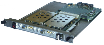
Figure 4-3 on page 4-12 shows an SFF Adapter module with a legacy ATM card.
Figure 4-3. SFF Adapter with ATM Module
Table 4-3 on page 4-7 identifies the modules that can be used with the SFF Adapter.
Installing Filler Panels
The airflow in an Optixia XM12 chassis is inefficient if load modules are installed in a few slots and the rest of the chassis is left open. For best cooling results, filler panels are required. It is required that filler panels are used in situations where the slots in the chassis are not all in use.
An empty Optixia XM12 chassis includes:
Prerequisites for Filler Panel Installation:
Filler Panel Installation Procedure:
Example: Slide the one-slot filler panel, with the Ixia logo at the top, into the correct slot. The panel slides in on the slot rails in the chassis. Secure the faceplate of the filler panel to the chassis with two of the supplied screws.
Cooling Fan Speed Control
The XM12 chassis automatically senses the temperature of specified modules and adjusts the cooling fan speed. If the system and board heat load is low enough, the cooling fan operates at a lower (quieter) speed.
The following modules have thermal sensors that report temperature readings:
Other modules control the fan speed by means of a fixed speed setting. For a list of supported modules, see Table 4-3 on page 4-7.
XM12 Sound Reducer Installation
The XM12 Sound Reducer (PN 942-0021) is an optional accessory that installs on the rear of the XM12 chassis to reduce the sound of the cooling fans. It reduces the sound by approximately 10 dB.
Refer to the following figure when performing the installation.
Figure 4-4. XM12 Sound Reducer Installation
- On the XM12 chassis rear, remove the four shoulder screws that hold the fan panel in place. Do not remove the fan panel.
- Attach the sound reducer mounting bracket to the fan panel using the same four shoulder screws removed in Step 1.
- Slide the sound reducer onto the mounting bracket.
- Secure the sound reducer onto the mounting bracket using the four pan-head screws included in the XM12 Sound Reducer kit.
Install XM12 Chassis
The following steps describe the procedure of installing an XM12 chassis:
- Locate the two holes above that line up with the rack and screw in the other two screws (preferably the upper hole or one right below that)
- Screw-in the bottom two screws all the way.
- Find two or four more screws and screw them in. Do this optionally, and only if the holes line up.
- Insert modules (ensure that any empty slots have the blank metal covers in them as marked in red in the image below).
.
Rack Mount Cautions
- Elevated Operating Ambient Temperature: If installed in a closed or multi-unit rack assembly, the operating ambient temperature of the rack environment may be greater than room ambient temperature. Therefore, consider installing the equipment in an environment that is compatible with the maximum allowable ambient temperature specified for the chassis (40° C).
- Reduced Air Flow: Install the equipment in a rack so that the amount of air flow required for safe operation of the equipment is not reduced.
Do not block the back or sides of the chassis, and leave approximately two inches of space around the unit for proper ventilation.- Mechanical Loading: Mount the equipment in the rack so that a hazardous condition is not caused due to uneven mechanical loading.
- Circuit Overloading: Consider the connection of the equipment to the supply circuit and the effect that overloading of the circuits might have on overcurrent protection and supply wiring. Pay attention to equipment nameplate ratings when addressing this concern.
- Reliable Earthing: Maintain reliable earthing (grounding) of rack-mounted equipment. Chassis frame should be screwed down to racks to ensure proper grounding path. In Addition, Pay special attention to supply connections other than direct connections to the branch circuit (such as use of power strips).
- Replacement of the power supply cord must be conducted by a Service Person. The same type cord and plug configuration shall be utilized.
High Performance Upgrade Kit
A standard XM12 chassis (with two 1.6 kW power supplies) can be converted to a high performance XM12 (with two 2.0 kW power supplies) using an upgrade kit that is available from Ixia. Request `Field Replaceable Unit, Power Supply Upgrade Kit' (FRU-OPTIXIAXM12-01) PN 943-0005.
Voice Quality Resource Module
Voice Quality Resource Module (VQM01XM) performs real-time processing of speech quality analysis using PESQ algorithm, on streams received on ports of the following load modules:
The VQM01XM communicates with load modules through the chassis backplane. A single VQM01XM module can perform PESQ analyses, including necessary decoding, on up to 300 narrowband streams concurrently in real time. The PESQ stats are published in Stats View just after the last RTP packet of the analyzed sequence is received on port.
Statistics and Measurements
The following real time metrics (Min, Max, and Average values) are provided by the Voice Quality Resource Module, depending on the application being run:
These statistics are available in aggregated mode and individual per stream, as part of `VoIP RTP Per Channel' statistics.
|
|
Did this document answer your question?
If not, let us know! |
|