PDF version of this section PDF version of entire manual

Get this 
section in PDF
Get entire 
manual in PDF

PreviousNextIndex


Chapter 5: Optixia XM2 Chassis


This chapter provides details about the Optixia XM2 chassis—its specifications and features.

The Optixia XM2 is the next generation portable chassis that is a combination of the Optixia architecture with the XM form factor. The 2-slot platform allows for higher port density load modules in a portable chassis.

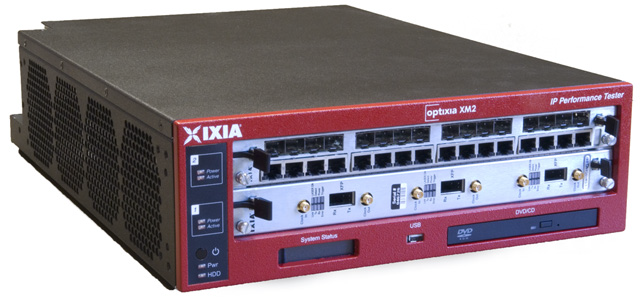
The Optixia XM2 Chassis has 2 slots for support of up to 2 single wide load modules. The Optixia XM2 supports all XM form factor load modules and many standard form factor load modules with improved system power and cooling. The Optixia XM2 was specifically designed to allow the hot-swapping of load modules, without requiring the chassis to be powered down. The Optixia XM2 is shown in Figure 5-1.

Note: The Optixia XM2 must only be operated in the horizontal position as shown in Figure 5-1.

Warning: To prevent accidental injury to personnel, do not leave unused SFP (or SFP+) ports on load modules uncovered. When transceivers are not installed, end caps must be used. For details, see Use End Caps on Open Ports on page 1-xxxvii.

Figure 5-1. Optixia XM2 Chassis

The Optixia family of chassis has improved data throughput between Load Modules and the chassis, with improved backplane performance.

The Optixia chassis provides improved modularity of major components to reduce downtime of a failed chassis and reduce the probability of needing to remove a failed chassis from the test environment. Among the modular features provided are:

The power supply is accessible from the back of the chassis. The hard drive is accessible from the bottom of the chassis.

Specifications

XM2 Chassis

The Optixia XM2 computer and chassis specifications are contained in
Table 5-1.
Table 5-1. Optixia XM2 Specifications
CPU
Intel Pentium Mobile, 2.0 GHz
Caution–Battery replacement
There is danger of explosion if battery is incorrectly replaced. Do not attempt to replace the battery.
Return to Ixia Customer Service for replacement with the same or equivalent type of battery. Ixia disposes of used batteries according to the battery manufacturer's instructions.
Memory
2 GB
Disk
250GB SATA Disk HD
USB Drive
DVD Drive is not present in newer versions of XM2 chassis (starting with 941-0003-07 and 941-0023-02).
Operating System
Windows XP Professional
Physical
Note: The Optixia XM2 must only be operated in the horizontal position as shown in Figure 5-1 on page 5-2.
Load Module Slots
2 XM form factor
Size
4.8 in. H x 20.0 in. W x 14.2 in. D
(12.2cm H x 50.8cm W x 36.1cm D)
Weight (empty)
25 lb (11.34 kg)
Avg. Shipping Wt.
30 lb (13.61 kg)
Shipping Vibration
FED-STD-101C, Method 5019.1/5020.1
Environmental
 
Temperature
 
Operating
41×F to 104×F, (5×C to 40×C)
Note: Some high-density/high performance load modules require a lower maximum ambient operating temperature than the standard for the chassis. When a load module that requires the lower maximum operating temperature is installed in an XM chassis, the maximum operating temperature of the chassis is adjusted downward to match the maximum operating temperature of the load module. The operating temperature range specification is specified in the published datasheet for each load module.
Storage
41×F to 122×F, (5×C to 50×C)
Humidity
 
Operating
0% to 85%, non-condensing
Storage
0% to 85%, non-condensing
Clearance
Sides: 4 in (10 cm); fan openings should be clear of all cables or other obstructions.
Power
100-240V 60/50Hz 12-6A
Caution: The socket/outlets used to power the unit must be installed near the equipment and be easily accessible because the power plug may be used to disconnect the unit from the power source.
Front Panel Switches
On/Off momentary power push button
Front Panel Connectors
 
USB
1 USB dual type A, 4-pin jack connector
Sync In
4-pin RJ11
Sync Out
4-pin RJ11
Front Panel Indicators
 
2 Paired LEDs above each slot position indicating Power and Active status
 
1 LED indicating chassis Power ON
1 LED indicating HDD operation
 
LCD on front panel to display chassis information
Rear Panel Connectors
 
Mouse
PS/2 6-pin DIN
You must use the supplied Y-cable when using the PS/2 mouse.
Keyboard
PS/2 6-pin DIN (with or without the Y-cable)
Monitor
HD-DB15 Super VGA
Printer
Female DB25 parallel port
Ethernet
RJ-45 10/100/1000Mbps Gigabit Ethernet Management Port
Serial
1 male DB9 ports
USB
2 USB dual type A, 4-pin jack connectors
Power
Male receptacle (IEC 60320-C13)
Noise
Condition:Ixia XM2
Front Back Right Left
Plugged in not started 56 54 57 58
Only CPU Running
On Low Speed 58 56 58 60
On Medium Speed-
On Full Speed 70 67 70 73

LEDs/LCD Display

The Optixia XM2 has the following set of front panel LEDs:
Table 5-2. Optixia XM2 LEDs
Label
Color
Description
Power
Green
For each load module slot, the Power LED is illuminated when the board is being powered.
When the Power LED is flashing, the board is being detected or initialized.
Active
Green
For each load module slot, the Active LED is illuminated when a Load Module in a particular slot is owned by you.
Pwr
Green
For the chassis, indicated Power ON
HDD
Green
For the chassis, indicates hard disk is active

LCD Display

An LCD display is provided on the chassis to indicate the status of the chassis without an external display device (monitor). The LCD operates in two modes:

Supported Modules

The modules that are supported on the Optixia XM2 are listed in Table 5-3..
Table 5-3. Optixia XM2 Supported Modules
Module
SFF - Requires Adapter
Function
HSE40GETSP1-01
HSE100GETSP1-01
HSE40/100GETSP1-01
 
40 and 100 Gigabit Ethernet 1-port, 2-slot CFP interface (Full feature)
dual-speed, 1-port, 2-slot CFP interface (Full feature)
HSE40GEQSFP1-01
 
1-port, 1-slot, QFSP interface (Full feature)
Xcellon-Ultra NP-01
 
12-port 10/100/1000 Mbps and 1-port 1GE aggregated and 1-port 10GE aggregated, Base T Ethernet copper, single-slot load module
Xcellon-Ultra XP-01
 
12-port 10/100/1000 Mbps and 1-port 1GE aggregated and 1-port 10GE aggregated, Base T Ethernet copper, single-slot load module
Xcellon-Ultra NG-01
 
12-port 10/100/1000 Mbps and 1-port 1GE aggregated and 1-port 10GE aggregated, Base T Ethernet copper, single-slot load module
ASM1000XMV12X-01
 
12-port 10/100/1000 Mbps and 1-port 1GE aggregated and 1-port 10GE aggregated, Base T Ethernet copper, single-slot load module
LSM1000XMSP12-01
 
12-Port Gigabit Ethernet Load Module, Dual-PHY RJ45 10/100/1000 Mbps and SFP fiber
LSM1000XMVDC4-01
LSM1000XMVDC4-NG
LSM1000XMVDC8-01
LSM1000XMVDC12-01
LSM1000XMVDC16-01
LSM1000XMVDC16NG
 
4/8/12/16-Port Dual-PHY RJ45 10/100/1000 Mbps and SFP fiber. FCoE enabled
LSM1000XMS12-01
 
10/100/1000 Ethernet 12 port module
LSM1000XMSR12-01
 
10/100/1000 Ethernet 12 port module, reduced feature set
LSM10GXM2XP-01
LSM10GXM2GBT-01
LSM10GXM2S-01
 
10 Gigabit Ethernet 2 port module, 1GHz, 1GB, Extra Performance.
Includes 10GBASE-T version and SFP+ version.
LSM10GXMR2-01
LSM10GXMR2GBT-01
LSM10GXMR2S-01
 
10 Gigabit Ethernet 2 port module, 400MHz, 128MB, single slot, reduced L2/3 support with limited L3 routing, Linux SDK, and L4-7 applications.
Includes 10GBASE-T version and SFP+ version.
LSM10GXM3-01
 
10 Gigabit Ethernet 3 port module
LSM10GXMR3-01
 
10 Gigabit Ethernet 3 port module, reduced feature set
LSM10GXM4-01
 
10 Gigabit Ethernet 4 port single slot, full-featured load module, 800MHz, 512MB. Full L2/7 support. Linux SDK, and L4-7 applications.
LSM10GXM4XP-01
LSM10GXM4GBT-01
LSM10GXM4S-01
 
10 Gigabit Ethernet 4 port module, 1GHz, 1GB, Extra Performance.
Includes 10GBASE-T version and SFP+ version.
LSM10GXMR4-01
LSM10GXMR4GBT-01
LSM10GXMR4S-01
 
10 Gigabit Ethernet 4 port module, 400MHz, 128MB, single slot, reduced L2/3 support with limited L3 routing, Linux SDK, and L4-7 applications.
Includes 10GBASE-T version and SFP+ version.
LSM10GXM8-01
 
10 Gigabit Ethernet 8 port single slot, full-featured module, 800MHz, 512MB. Full L2/7 support. Linux SDK, and L4-7 applications.
LSM10GXM8XP-01
LSM10GXM8GBT-01
LSM10GXM8S-01
 
10 Gigabit Ethernet 8 port module, 800MHz, 1GB, Extra Performance.
Includes 10GBASE-T version and SFP+ version.
LSM10GXMR8-01
LSM10GXMR8GBT-01
LSM10GXMR8S-01
 
10 Gigabit Ethernet 8 port module, 400MHz, 128MB, single slot, reduced L2/3 support with limited L3 routing, Linux SDK, and L4-7 applications.
Includes 10GBASE-T version and SFP+ version.
NGY-NP8-01
NGY-NP4-01
NGY-NP2-01
 
10 Gigabit Application Network Processor Load Module, 2/4/8-Port LAN/WAN, SFP+ interface
AFM1000SP-01
X
10/100/1000 3 port Stream extraction module
LSM1000XMV4-01
 
4-port Dual-PHY (RJ45 and SFP) 10/100/1000 Mbps Ethernet load module
LSM1000XMVR4-01
 
4-port Dual-PHY (RJ45 and SFP) 10/100/1000 Mbps Ethernet load module, reduced performance
LSM1000XMV8-01
 
8-port Dual-PHY (RJ45 and SFP) 10/100/1000 Mbps Ethernet load module
LSM1000XMVR8-01
 
8-port Dual-PHY (RJ45 and SFP) 10/100/1000 Mbps Ethernet load module, reduced performance
LSM1000XMV12-01
 
12-port Dual-PHY (RJ45 and SFP) 10/100/1000 Mbps Ethernet load module
LSM1000XMVR12-01
 
12-port Dual-PHY (RJ45 and SFP) 10/100/1000 Mbps Ethernet load module, reduced performance
LSM1000XMV16-01
 
16-port Dual-PHY (RJ45 and SFP) 10/100/1000 Mbps Ethernet load module
LSM1000XMVR16-01
 
16-port Dual-PHY (RJ45 and SFP) 10/100/1000 Mbps Ethernet load module, reduced performance
CPM1000T8
X
Special 10/100/1000 Ethernet load module
MSM10G1-02
X
LAN/WAN/POS Multimode load module
LM100TXS2
X
10/100 Ethernet load module
LM100TXS8
X
8-port multilayer 10/100Mbps Ethernet load module
LM100TX8
X
8-port 10/100Mbps Ethernet, reduced features
LM1000STXR4
X
4-port Dual-PHY (RJ45 and SFP) 10/100/1000 Mbps Ethernet load module, reduced feature set
LM1000STXS2
X
2-port Dual-PHY (RJ45 and SFP) 10/100/1000 Mbps Ethernet load module.
LM1000STXS4
X
4-port Dual-PHY (RJ45 and SFP) 10/100/1000 Mbps Ethernet load module
LM1000STXS4-256
X
4-port Dual-PHY (RJ45 and SFP) 10/100/1000 Mbps Ethernet load module; -256 version has 256MB of processor memory per port
LM1000STX2
X
2-port Dual-PHY (RJ45 and SFP) 10/100/1000 Mbps Ethernet load module
LM1000STX4
X
4-port Dual-PHY (RJ45 and SFP) 10/100/1000 Mbps Ethernet load module
LM1000TXS4
X
4-port 10/100/1000 Mbps Base-T Ethernet copper
LM1000TXS4-256
X
4-port 10/100/1000 Mbps Base-T Ethernet copper;
-256 version has 256MB of processor memory per port
LM1000TX4
X
4-port 10/100/1000 Mbps Base-T Ethernet copper, reduced features
LM1000SFPS4
X
4-port Gigabit Ethernet fiber
ALM1000T8
X
Special 10/100/1000 Ethernet load module
ELM1000ST2
X
Special 10/100/1000 Ethernet load module
LSM10G1-01
X
10 Gigabit Ethernet load module
LSM10G1-01M
X
10 Gigabit Ethernet load module
LSM10GL1-01
X
10 Gigabit Ethernet load module
LSM1000POE4-02
X
4-port PoE load module
PLM1000T4-PD
X
Power over Ethernet load module
LM622MR
X
ATM/POS load module
LM622MR-512
X
ATM/POS load module
MSM2.5G1-01
X
OC-48c load module
VQM01XM
 
Voice Quality Resource Module performs real-time processing of speech quality analysis using PESQ algorithm, on streams received on ports of the following load modules:
  • Xcellon-Ultra NP-01
  • Xcellon-Ultra XP-01
  • Xcellon-Ultra NG-01
  • ASM1000XMV12X-01
  • LSM1000XMV4-01
  • LSM1000XMV16-01
  • ALM1000TS
  • CPM1000TS
EIM10G4S
SFP adapter
10 Gigabit Ethernet LAN Impairment module, 1-slot with 4-ports of SFP+ interfaces
EIM1G4S
SFP adapter
1Gigabit Ethernet LAN Impairment module, 1-slot with 4-ports of SFP interfaces
LavaAP40/100GE 2P
CFP to QSFP
This is the dual speed 40GE/100GE Ethernet Lava load module with Accelerated Performance. Each load module consists of 2-ports and 1-slot with CFP MSA interfaces. This load module supports full feature for layer 1 to layer 7 testing
LavaAP40/100GE 2RP
CFP to QSFP
This is the dual speed 40GE/100GE Ethernet Lava load module with data plane support only. It is an economic alternative to the Accelerated Performance load module, perfectly suitable for testing layer 1 to layer 3 applications that does not require routing protocol emulation. Each load module consists of 2-ports and 1-slot with CFP MSA interfaces

Rack Mount Instructions

Caution: If this unit is installed in a rack mount, observe the following precautions:

    1. Elevated Operating Ambient Temperature: If installed in a closed or multi-unit rack assembly, the operating ambient temperature of the rack environment may be greater than room ambient temperature. Therefore, consider installing the equipment in an environment that is compatible with the maximum allowable ambient temperature specified for the chassis (40° C).
    2. Reduced Air Flow: Install the equipment in a rack so that the amount of air flow required for safe operation of the equipment is not reduced.
      Do not block the back or sides of the chassis, and leave approximately two inches of space around the unit for proper ventilation.
    3. Mechanical Loading: Mount the equipment in the rack so that a hazardous condition is not caused due to uneven mechanical loading.
    4. Circuit Overloading: Consider the connection of the equipment to the supply circuit and the effect that overloading of the circuits might have on overcurrent protection and supply wiring. Pay attention to equipment nameplate ratings when addressing this concern.
    5. Reliable Earthing: Maintain reliable earthing (grounding) of rack-mounted equipment. Pay special attention to supply connections other than direct connections to the branch circuit (such as use of power strips).

Installing Rack-Mount Ear Brackets

To mount the Optixia XM2 chassis into an equipment rack, first attach the rack-mount ears to the sides of the chassis.

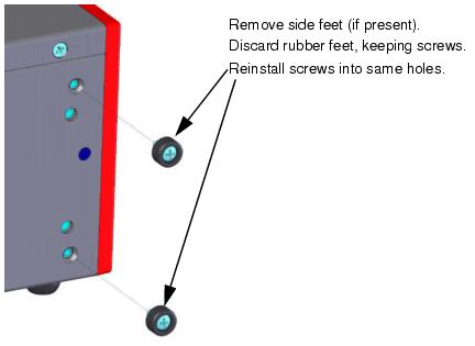
  1. If side feet are present (on left side of chassis) remove them. Discard the rubber feet, but keep the screws. See Figure 5-2 on page 5-11.
  2. Reinstall the screws removed in step 1 (into the same holes).
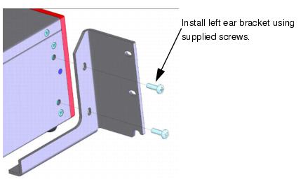
  3. Install left-side ear bracket (Ixia PN 652-0688-02) using supplied screws (PN 600-0105). See Figure 5-3 on page 5-11.
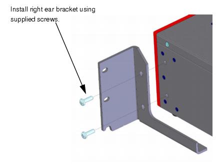
  4. Install right-side ear bracket (Ixia PN 652-0688-01) using supplied screws (PN 600-0105). See Figure 5-4 on page 5-12.
  5. Figure 5-2. Remove Side Feet (If Present)

Figure 5-3. Install Left Ear Bracket

Figure 5-4. Install Right Ear Bracket

Hot-Swap Procedure

Each Optixia XM2 chassis provides the ability of removing and reinstalling a Load Module without requiring the removal of power from the rest of the chassis. The process of removing/installing a Load Module does not impact either the operation of the OS or load modules installed in the chassis.

The hot-swap procedure is detailed in Appendix D, Hot-Swap Procedure.
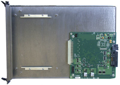
SFF Adapter Module

The Optixia XM adapter module allows legacy modules to be fit into the XM2 chassis. Figure 5-5 on page 5-13 shows an SFF adapter module.

Figure 5-5. SFF Adapter

A legacy module is inserted into the front of the adapter module and connects to the pins in the rear of the adapter. The entire assembly can then be inserted into either Optixia XM2 slot.

Once an adapter module is installed in a chassis, legacy load modules can be hot-swapped without removing the adapter module from the chassis.

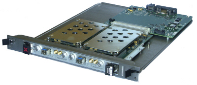
Figure 5-6 on page 5-13 shows an SFF Adapter module with a legacy ATM card.

Figure 5-6. SFF Adapter with ATM Module

Table 5-3 on page 5-5 identifies the modules that can be used with the SFF Adapter.

Installing Filler Panels

The airflow in an Optixia XM2 chassis can be inefficient if a load module is installed in one slot and the other is left open. For best cooling results, filler panels are required. Filler panels must be used in situations where the slots in the chassis are not all in use.

An empty Optixia XM2 chassis includes:

Prerequisites for Filler Panel Installation:

The technician should use industry-standard grounding techniques, such as wrist and ankle grounding straps, to prevent damage to electronic components on any Ixia Load Modules.

Filler Panel Installation Procedure:

ESD Caution: Use industry-standard grounding techniques to prevent Electrostatic Damage to the delicate electronic components on the Ixia Load Modules.

Example: Slide the one-slot filler panel, with the Ixia logo at the top, into the correct slot. The panel slides in on the slot rails in the chassis. Secure the faceplate of the filler panel to the chassis with two of the supplied screws.

Caution: Use extreme care to prevent damage to delicate electronic components on an adjacent load module.
Not using filler panels could cause random failures in port operations or damage installed modules.

.Cooling Fan Speed Control

The XM2 chassis automatically senses the temperature of specified modules and adjusts the cooling fan speed. If the system and board heat load is low enough, the cooling fan operates at a lower (quieter) speed.

The following modules have thermal sensors that report temperature readings:

Other modules control the fan speed by means of a fixed speed setting. For a list of supported modules, see Table 5-3 on page 5-5.


PreviousNextIndex

Did this document 
answer your question?

If not, let us know!


Voice: (818) 871-1800
Fax: (818) 871-1805
info@ixiacom.com