section in PDF
manual in PDF


|
|
|
| |
| Get this section in PDF |
Get entire manual in PDF |
|
Chapter 23: IXIA Network Processor Load Modules
This chapter provides details about Ixia's Xcellon-Ultra XP and Xcellon-Ultra NP load modules—the specificatons, features, and functionality. It also provides details on Xcellon-Ultra load module when it operates in IxN2X mode.
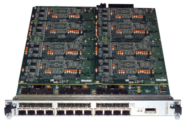
Ixia's Gigabit and 10 Gigabit Ethernet Network Processor load modules Xcellon-Ultra XP and Xcellon-Ultra NP. These are Ethernet modules with additional aggregation capability. Each features 12 ports of 10/100/1000Mbps Ethernet configurable in either aggregation mode, stream mode, or as 1 port of 10GE aggregation. The Xcellon-Ultra module can provide 144 GigE ports in the Optixia XM12 or 24 GigE ports in the Optixia XM2. The Xcellon-Ultra XP-01 module is shown in Figure 23-1.
IxN2X capability is added to the regular Xcellon-Ultra load module to use it in IxN2X mode. Xcellon-Ultra XP and NP and Xcellon-Ultra NG load modules share similar physical properties. In addition to the physical properties, Xcellon-Ultra NG supports IxN2X mode.
Figure 23-1. Xcellon-Ultra XP-01 Application Load Module
The Xcellon-Ultra module offers complete Layer 2-7 network and application testing functionality in a single Optixia XM load module. The twelve Gig Ethernet ports may either be used individually or aggregated through a 10 Gigabit Ethernet port. This architecture allows the processing power and resources of up to twelve per-port CPUs to be combined into one physical port, providing the highest Layer 4-7 line-rate performance, unmatched in any other Layer 4-7 test solution. Each test port supports wire-speed Layer 2-3 traffic generation and analysis, high-performance routing/bridging protocol emulation, and true Layer 4-7 application traffic generation and subscriber emulation. Using 12 GbE ports per module, ultra-high density test environments can be created for auto-negotiable 10/100/1000 Mbps Ethernet over copper as well as fiber. With 12 slots per Optixia XM12 chassis, up to 144 Gigabit Ethernet and 12 10GbE test ports are available in a single test system.
Application Layer Performance Testing
The Gigabit Ethernet Xcellon-Ultra module supports high performance testing of content-aware devices and networks through the Aptixia IxLoad application. IxLoad creates real-world traffic scenarios at the TCP/UDP (Layer 4) and Application (Layer 7) layers, emulating clients and servers for Web (HTTP, SSL), FTP, Email (SMTP, POP3, IMAP), Streaming (RTP, RTSP), Video (MPEG2, MPEG4, IGMP), Voice (SIP, MGCP), and services such as DNS, DHCP, LDAP and Telnet. Each GE XMV port can be independently configured to run different protocols and client/server scenarios.
Real-time Transport Protocol (RTP) Feature
For the Xcellon-Ultra XP and NP modules, the RTP engine built into the FPGA can generate and terminate audio streams (video and data traffic is an option, too). The RTP engine works together with the VoIP Peer signaling protocols present in IxLoad. On a physical port the traffic is a mixture of signaling traffic generated and analyzed by PCPU, RTP traffic generated by CPCU, and RTP traffic generated by hardware.
The RTP feature is selectable from the Port Properties—Operation Mode tab in IxExplorer. For details, see the IxExplorer User Guide, Chapter 18, topic Port Properties for Xcellon-Ultra and ASM1000XMV12X Modules.
Modes of Operation
The Xcellon-Ultra modules can operate in three different modes providing a flexible, scalable and powerful layer 4-7 performance.
Non-Aggregated (Normal) Mode
In this mode, the twelve 10/100/1000Mbps ports provide L2-L7 XMV functionality. Each port is capable of providing high performance packet generation and application layer testing by employing its own port CPU resources as well as the dedicated hardware stream engine. In this mode the 10GE Aggregation Port is disabled.
Gigabit Aggregated Mode
Gigabit Aggregated Mode allows the twelve PCPUs to be assigned to any of 12 GbE test ports through the switch fabric. Aggregation of the processing power allows application layer testing at line rate regardless of the test objective. A cluster of PCPU's can be assigned to any of the physical ports. Multiple clusters and their assigned physical ports can exist on the same module. Aptixia applications transparently configures the available PCPU resources and make the assignment to the physical port(s) to achieve the test objectives. This mode is exclusive to L4-7 testing and there is no support for hardware stream engine. In this mode the 10GE Aggregation Port is disabled.
10GE Aggregated Mode
In 10GE Aggregated Mode, all of the twelve PCPUs are assigned to the 10GE Aggregation Port through the switch fabric. Aggregation of the processing power allows application layer testing at line rate (10 Gbps). Aptixia applications transparently configure the PCPU resources to achieve the test objectives. This mode is exclusive to L4-7 testing and there is no support for hardware stream engine. In this mode the twelve Gigabit ports are disabled.
Flexible Packet Generation
Each Xcellon-Ultra test port is capable of generating precisely controlled network traffic at up to wire speed of the network interface using Ixia's IxExplorer test application. Up to millions of packet flows can be configured on each port with fully customizable packet header fields. Flexible header control is available for Ethernet, IPv4/v6, IPX, ARP, TCP, UDP, VLANs, QinQ, MPLS, GRE, and many others. Payload contents can also be customized with incrementing/decrementing, fixed, random, or user-defined information. Frame sizes can be fixed, varied according to a pattern, or randomly assigned across a weighted range. Rate control can be flexibly defined in frames per second, bits per second, percentage of line rate, or inter-packet gap time.
Real-Time Latency
Packets representing different traffic profiles can be associated with Packet Group Identifiers (PGIDs). The receiving port measures the minimum, maximum, and average latency in real time for each packet belonging to different groups. Measurable latencies include:
- Instantaneous latency and inter-arrival time where each packet is associated with one group ID
- Latency bins, where PGIDs can be associated with a latency range
- Latency over time, where multiple PGIDs can be placed in `time buckets' with fixed durations
- First and last time stamps, where each PGID can store the timestamps of first and last received packets
Transmit Scheduler
There are two modes of transmission are available - Packet Stream and Advanced Stream Scheduler:
Packet Stream Scheduler
In Packet Stream Scheduler mode, the transmit engine allows configuration of up to 4096 unique sequential stream groupings on each port. Multiple streams can be defined in sequence, each containing multiple packet flows defined by unique characteristics. After transmission of all packets in the first stream, control is passed to the next defined stream in the sequence. After reaching the last stream in the sequence, transmission may either cease, or control may be passed on to any other stream in the sequence. Therefore, multiple streams are cycled through, representing different traffic profiles to simulate real network traffic.
Advanced Stream Scheduler
In Advanced Stream Scheduler mode, the transmission of stream groupings is interleaved per port. For example, assume a port is configured with three streams. If Stream 1 is defined with IP packets at 20% of line rate, Stream 2 is defined with TCP packets at 50% of line rate, and Stream 3 is defined with MPLS packets at 30% of line rate, data on the port is transmitted at an aggregate utilization of 100% with interleaved IP, TCP, and MPLS packets.
Extensive Statistics
- Real-time 64-bit frame counts and rates
- Spreadsheet presentation format for convenient manipulation of statistics counters
- Eight Quality of Service counters (supporting 802.1p, DSCP, and IPv4 TOS measurements)
- Six user-defined statistics that use a trigger condition
- Extended statistics for ARP, ICMP, and DHCP
- Transmit stream statistics for frame counts and rate
- External logging to file for statistics and alerts
- Audible and visual alerts with user-definable thresholds
Data Capture
Each port is equipped with 64 MB of capture memory, capable of storing tens of thousands of packets in real time. The capture buffer can be configured to store packets based on user-defined trigger and filter conditions. Decodes for IPv4, IPv6, UDP, ARP, BGP-4, IS-IS, OSPF, TCP, DHCP, IPX, RIP, IGMP, CISCO ISL, VLAN, and MPLS are provided.
Data Integrity
As packets traverse through networks, IP header contents may change, resulting in the recalculation of packet CRC values. To validate device performance, the data integrity function of Gigabit Ethernet Xcellon-Ultra modules allows packet payload contents to be verified with a unique CRC that is independent of the packet CRC. This ensures that the payload is not disturbed as the device changes header fields.
Sequence and Duplicate Packet Checking
Sequence numbers can be inserted at a user-defined offset in the payload of each transmitted packet. Upon receipt of the packets by the Device Under Test (DUT), out-of sequence errors or duplicated packets are reported in real time at wire-speed rates. You can define a sequence error threshold to distinguish between small versus big errors, and the receive port can measure the amount of small, big, reversed, and total errors. Alternatively, you can use the duplicate packet detection mode to observe that multiple packets with the same sequence number are received and analyzed.
Routing/Bridging Protocol Emulation
Ixia's Gigabit Ethernet Xcellon-Ultra modules support performance and functionality testing using routing/bridging protocol emulation through the Aptixia IxNetwork and Aptixia IxAutomate applications. Protocols supported include IPv4/IPv6 routing (BGP-4, OSPF, IS-IS, and RIP), MPLS (RSVP-TE, LDP, L2 MPLS VPNs, L3 MPLS VPNs, and VPLS), multicast (IGMP, MLD, and PIM-SM), and bridging (STP, RSTP, MSTP). Highly scalable scenarios can be created emulating up to thousands of routers advertising millions of routes per test port. Up to wire-speed Layer 2/3 traffic can be automatically created to target routes and MPLS tunnels.
Part Numbers
The part numbers are shown in Table 23-1.
Specifications
The load module specifications are contained in Table 23-2 on page 23-6. The limitations of -3, Layer 2/3, and Layer 7 cards are discussed in Ixia Load Modules on page 1-5.
Port LEDs
Each Xcellon-Ultra port incorporates a set of two LEDs, as described in Table 23-3. The 1GbE LEDs are used in Normal and 1GbE Aggregate modes. They behave identically in both modes, except that due to switch limitations, the `CRC Error' LED is non-operational in 1GE Aggregate mode (that is, it never indicates error). The 1GE LEDs are disabled (always off) in 10GE Aggregate mode.
10GE LEDs are disabled (always off) in Normal and 1GE Aggregate modes. In 10GE Aggregate mode, the two LEDs behave as described in Table 23-4.
Statistics
Statistics for Xcellon-Ultra cards, under various modes of operation may be found in the Appendix B, Available Statistics.
|
|
Did this document answer your question?
If not, let us know! |
|