PDF version of this section PDF version of entire manual

Get this 
section in PDF
Get entire 
manual in PDF

PreviousNextIndex


Chapter 6: XG12 Chassis


This chapter provides details about the XG12 chassis—its specifications and features.

The XG12 Chassis is the next generation high performance platform capable of supporting all XM form factor load modules, including full chassis configurations of the Xcellon load modules. It is a 12-slot chassis with increased total power capacity available for all load modules and front-to-back airflow delivery along with increased bandwidth from the CPU to the load modules.

The chassis provides improved modularity and access to the major components to reduce downtime of a failed chassis and to reduce the probability of needing to remove a failed chassis from the test environment. The four separate modules that make up the chassis are shown in Table 6-1.
Table 6-1. XG12 Part Numbers and Modules
Part Number
Description
941-0017
XG12, 12-Slot Chassis Frame Module
942-0031
XG12, 12-Slot Chassis Fan Module
942-0032
XG12, 12-Slot Chassis Power Supply Module
942-0033
XG12, 12-Slot Chassis Processor Module

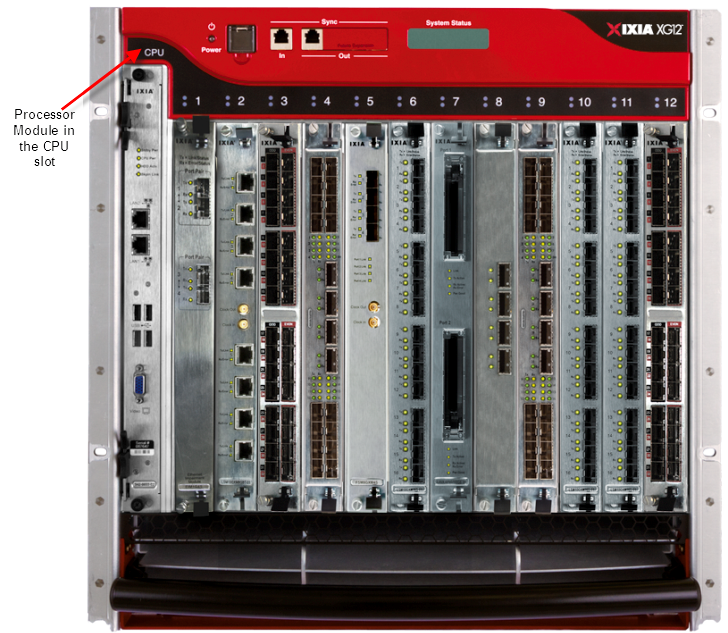
The XG12, shown in Figure 6-1, allows the hot-swapping of load modules, without requiring the chassis to be powered down. The Processor module for the XG12 chassis is not hot swappable.

The Processor Module is plugged into the front of the chassis. The power supplies and fans are accessible from the rear of the chassis. Each of the modular components is capable of being removed in the field and replaced with minimum downtime.

Figure 6-1. XG12 Chassis

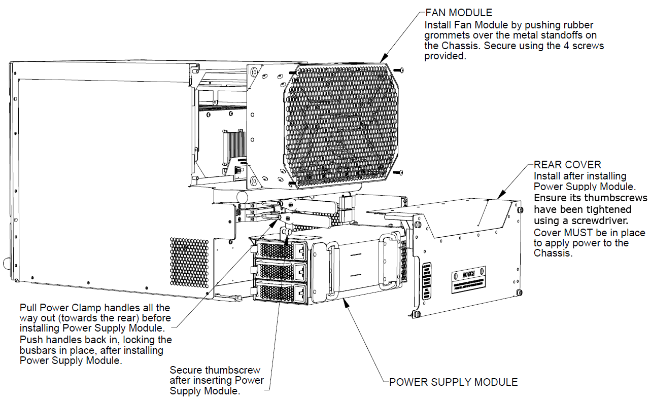
The component modules of the XG12 chassis are shown in the following figure:

Specifications

The XG12 chassis specifications are contained in the following tables:.
Table 6-2. XG12 Processor Module Specifications
Processor Module
Field replaceable and removable processor card module with an Intel 2.26 GHz Core™ 2 Duo processor with 4 GB CPU memory, and 250 GB SATA hard drive
Memory
4GB
Hard Disk Drive
250GB
Operating System
Windows 7
 
Caution–Battery replacement
There is danger of explosion if battery is incorrectly replaced. Do not attempt to replace the battery.
Return to Ixia Customer Service for replacement with the same or equivalent type of battery. Ixia disposes of used batteries according to the battery manufacturer's instructions.
 
Note: The serial number for the Processor Module is located on module itself. This is used as the overall chassis serial number.

Table 6-3. XG12 Chassis Specifications
Size
  • 19.0 in. W x 19.21 in. H x 27.2 in. D
  • 48.26cm W x 48.79cm H x 69.09cm D
  • 11 rackmount units (11RU)
Load Module Slots
12 (compatible with Ixia XM form factor load modules)
Chassis Power
The chassis requires three single phase, 200-240VAC, 50/60Hz circuits, each capable of providing 3680 watts. These circuits must provide protection against over-currents, short circuits and earth faults for the XG12 chassis. A 20A circuit breaker for each circuit is also required.
All three power cords must be plugged into their single phase 200-240VAC, 50Hz/60Hz power sources at the same time for correct operation of the chassis.
Note: The chassis power supplies are interlocked with the rear cover which must be installed for them to be enabled. After removing or installing the rear panel, ensure thumbscrews have been tightened down with a 'Flat Blade' screwdriver.
Note: The load module power is enabled by the Ixia server program. If it is not running, the load modules will not be powered on.
Power Cords
All three power cords are required to operate the XG12 chassis power supplies.
Power Cord shipments:
  • Ixia provides three power cords that are configured and rated to meet the specifications of the target country where the chassis is being installed
  • For North American customers, the power cords have NEMA L6-20P plugs for attachment to the power source and IEC-60320-C19 connectors that attach to the XG12 chassis
  • For International shipments, the power cords supplied has plugs suitable for each destination country's power source and IEC-60320-C19 connectors that attach to the XG12 chassis
  • The XG12 chassis is CE marked and UL™ certified when using the 200-240VAC power cords supplied with the chassis. However, these certifications for the chassis safety approvals are only valid when the unit is operating from all three 200-240VAC main power sources
Chassis Weights
Frame:
  • 64 lbs. (29.1 kg) empty, component weight
  • 97 lbs. (44.1 kg) average shipping weight (with filler panels)
Fan module:
  • 10.2 lbs. (4.63 kg) component weight
  • 17.3 lbs. (7.86 kg) average shipping weight
Power Supply module:
  • 28 lbs. (12.72 kg) component weight
  • 35.1 lbs. (15.95 kg) average shipping weight
Processor module:
  • 2.7 lbs. (1.23 kg) component weight
  • 8.5 lbs. (3.86 kg) average shipping weight
Warning: Total chassis weight, without any load modules installed is 104.9 lbs. (47.6 kg). Do not attempt to lift the fully assembled chassis.
Fan Module
Field replaceable chassis fan assembly that is easily installed and removed.
Air flow Clearance
12 inches is required at the rear of the chassis.
24 inches of clearance is preferred.
Power Supply Module
Field replaceable power supply module that is easily installed and removed.
There are three 2825W power supplies in the Power Supply Module.
Each power supply may be removed or replaced separately.
Timing Sources
Internal clock, synchronized with another Ixia chassis, GPS AFD-1unit, AFD2 IRIG-B unit or with the Timing Distribution Module.
Shipping Vibration
FED-STD-101C, Method 5019.1/5020.1
Operating temperature
41×F to 104×F, (5×C to 40×C)
Note: Some high-density/high performance load modules require a lower maximum ambient operating temperature than the standard for the chassis. When a load module that requires the lower maximum operating temperature is installed in an XM chassis, the maximum operating temperature of the chassis is adjusted downward to match the maximum operating temperature of the load module. The operating temperature range specification is specified in the published datasheet for these load modules.
Storage temperature
41oF to 122oF, (5oC to 50oC)
Operating Humidity
0% to 85%, non-condensing
Storage Humidity
0% to 85%, non-condensing
Noise
The XG12 chassis running at maximum fan speed capacity may produce noise levels up to 87 dB(A). This is measured per the GR-63-CORE, Issue 1, paragraph 5.6.3 specification. The use of appropriate ear protection is recommended to protect against hearing impairment. Consult local health and safety regulations for recommended maximum exposure levels for noise and ear protection devices.
 
Shown below are the maximum XG12 chassis sound levels measured according to GR-63-CORE, Issue 1, Paragraph 5.6.3.
  • Front: 83.5 dB(A)
  • Left Side: 84.2 dB(A)
  • Rear: 86.5 dB(A)
  • Right Side: 84.4 dB(A)

Hearing Protection: The XG12 chassis generates noise levels above 80 dB(A). Ear protection must be worn. The use of appropriate ear protection is recommended to protect against hearing impairment. Consult local health and safety regulations for recommended maximum exposure levels for noise and ear protection devices.

Table 6-4. XG12 Chassis controls and indicators
Front Panel Switches
On/Off momentary power push button
Monitor
HD-DB15 Super VGA
Ethernet
Two RJ-45 10/100/1000Mbps Gigabit Ethernet Management Port.
USB
4 USB dual type A, 4-pin jack connectors
Sync In
Single Sync In jack with a 4-pin RJ11
Sync Out
Single Sync Out jack with a 4-pin RJ11
Front Panel Indicators
 
2 Paired LEDs above each slot position indicating Power and Active status.
 
2x16 LCD on front panel indicating chassis information.

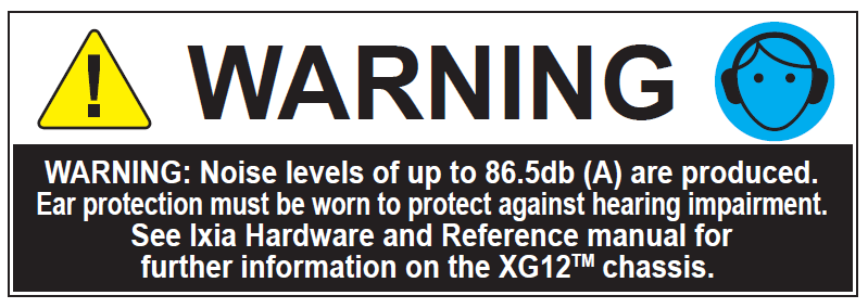
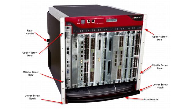
Figure 6-2. Safety Features

XG12 chassis installation precautions:

LEDs/LCD Display

The XG12 chassis has front panel LEDs for each load module slot.
Table 6-5. XG12 LEDs
Label
Color
Description
Power
Green
When the Power LED is flashing, the board is being detected or initialized.
The Power LED is illuminated when the board is powered..
In Use
Green
The Active LED is illuminated when a user has taken ownership of the load module.

LCD Display

An LCD display is provided on the chassis to indicate the status of the chassis without an external display device (monitor). The LCD operates in two modes:

CPU Slot LED Definitions

The specifications of LEDs for the Processor module and the LEDs above the Processor module slot are shown in the following table:

ESD Discharge Warning: Operator intervention may be required to power cycle the unit or restart a software program in the event the unit is upset by electrostatic discharge.

Table 6-6. LED Specifications
 
LED
Color
Description
On the chassis front face
CPU card Slot LED
Yellow
The backplane is initializing.
 
 
Green
The backplane has initialized
Processor module - front panel
Stdby Pwr LED
 
Green
5V Stand-by power is available
 
CPU Pwr LED
Green
CPU Card power is available
 
HDD Act LED


Bkpln Link LED
Green
PCIe link to backplane is up
Processor module - Ethernet LEDs for each management port
Link LED
Green
Port has link
 
Act LED
 
Flashes when port has activity

Supported Modules

The modules that are supported on the XG12 are listed in the following table.
Table 6-7. Supported Modules
Family
Module
Function
XM Form Factor (XMFF) load modules
Xcellon-Flex™ High density 10GbE products
  • Xcellon-FlexAP10G16S 10 Gigabit Ethernet LAN Load Module, L2-7 Accelerated Performance, a 1-slot module with 16-ports of SFP+ interfaces
  • Xcellon-FlexFE10G16S 10 Gigabit Ethernet LAN Load Module, L2-3 Full Emulation Performance, a 1-slot module with 16-ports of SFP+ interfaces
 
Xdensity™ Ultra-high density 10GbE
Xdensity, XDM10G32S, Ultra-high density, 10-Gigabit Ethernet load module with 32-ports of SFP+ interfaces and L2-3 data plane support
 
Xcellon-Flex™ High density 10GbE and 40 GE products
  • Xcellon-FlexAP10/4016SQ 10/40 Gigabit Ethernet Accelerated Performance Load Module, 16-Ports of SFP+ interfaces and 4-ports of QSFP 40 GE interfaces with full performance L1-7 support
  • Xcellon-FlexFE40G4Q 40 Gigabit Ethernet Full Emulation Load Module, 4-ports of QSFP 40 GE with L1-3 support
 
K2 Higher Speed Ethernet product line
  • HSE40GETSP1-01, 40-Gigabit Ethernet Load Module, 1-port, 2-slots, with the CFP MSA interface
  • HSE100GETSP1-01, 100- Gigabit Ethernet Load Module, 1-port, 2-slots, with the CFP MSA interface
  • HSE40/100GETSP1-01 Dual-Speed, 1-port, 2-slots, with CFP MSA interface
  • HSE40/100GETSPR1-01, Dual Speed, 40 and 100-Gigabit Data Plane Ethernet Load Module, 1-port, 2-slots, with the CFP MSA interface
  • HSE40GEQSFP1-01, 40-Gigabit Ethernet Load Module, 1-port, 1-slot with the QSFP+ pluggable interface for multimode fiber, 850nm, or QSFP+ copper cables
 
Xcellon Ultra™ High Performance Application Test product line
Xcellon-Ultra NP-01, Application Network Processor Load Module, 1-10G XFP port and/or 12-Ports of Dual-PHY (SFP fiber and RJ45 copper) 10/100/1000 Mbps
 
NGY High Density 10 Gigabit Ethernet product line
  • LSM10GXMR2/4/8-port, reduced performance, load modules with the XFP interface
  • LSM10GXM2/4/8XP-port, Extra performance, load modules with the XFP interface
  • LSM10GXM2S/4S/8S-port, Extra performance, load modules with the SFP+ interface
  • LSM10GXM2S/4S/8S-port, reduced performance, load modules with the SFP+ interface
  • LSM10GXM2GBT/4GBT/8GBT-port, Extra performance, load modules with the 10GBASE-T interface
  • LSM10GXM2GBT/4GBT/8GBT-port, reduced performance, load modules with the 10GBASE-T interface
 
Fibre Channel load module products
  • FCMGXM4S-01, 4-Port Fibre Channel Load Module, with 2Gbps, 4Gbps, and 8Gbps support, SFP+ interface
  • FCMGXM8S-01, 8-Port Fibre Channel Load Module, with 2Gbps, 4Gbps, and 8Gbps support, SFP+ interface
 
ImpairNet Load module products
  • ImpairNet EIM1G4S Gigabit Ethernet LAN Impairment module, 1-slot with 4-ports of SFP interfaces
  • ImpairNet EIM10G4S 10 Gigabit Ethernet LAN Impairment module, 1-slot with 4-ports of SFP+ interfaces
 
Voice Quality module
VQM0001, Resource module, for real time quality of voice measurement. Must purchased with VQM0001-B1, Solution Bundle, Resource module with IXLOAD-PESQ and IXLOAD-AUDIO-CODECS software license
 
NGY NP High Density 10GbE Application Test product line
  • NGY-NP8-01, 10 Gigabit Application Network Processor Load Module, 8-Port LAN/WAN, SFP+ interface
  • NGY-NP4-01, 10 Gigabit Application Network Processor Load Module, 4-Port LAN/WAN, SFP+ interface
  • NGY-NP2-01, 10 Gigabit Application Network Processor Load Module, 2-Port LAN/WAN, SFP+ interface
 
High Density Gigabit Ethernet product line
  • LSM1000XMVDC 4/8/12/16-port, full performance, load modules with dual-phy SFP fiber and 10/100/1000Mbps RJ45 copper
  • LSM1000XMVR4/8/12/16-port, reduced performance, load modules with dual-phy SFP fiber and 10/100/1000Mbps RJ45 copper
  • LSM1000XMSP12-01, Gigabit Ethernet, Load Module, 12-Ports Dual-PHY (SFP fiber and RJ45 copper) 10/100/1000 Mbps
Standard Form Factor (SFF) load modules for XG12 chassis
Note: Requires 944-0007 Adapter Card for XM Chassis installations
Gigabit Ethernet TX, TXS, STX and STXS products
  • LM100TX8, 100MB Ethernet Load Module, 8-Port 10/100Mbps, L2-3 data plane support only
  • LM100TXS8, 10/100Mbps Ethernet Load Module, 8-Port RJ45, 64MB Port CPU memory
  • LM100TXS2, 10/100Mbps Ethernet Load Module, 2-Port RJ45, 64MB Port CPU memory
  • LM1000STX4, Gigabit Ethernet Load Module, 4-Port Dual-PHY (RJ45 and SFP) 10/100/1000 Mbps, L2-3 data plane support only
  • LM1000STX2, Gigabit Ethernet Load Module, 2-Port Dual-PHY (RJ45 and SFP) 10/100/1000 Mbps, L2-3 data plane support only
  • LM1000STXS2, Gigabit Ethernet Load Module, 2-Port Dual-PHY (RJ45 and SFP) 10/100/1000 MbpsLM1000STXS4-256, Gigabit Ethernet Load Module, 4-Port Dual-PHY (RJ45 and SFP) 10/100/1000 Mbps
 
10 Gigabit Ethernet LSM products
  • LSM10G1-01, 10 Gigabit Ethernet Load Module, 1-Port, Full L2-7 support, requires interface adapter module
  • Interchangeable interface adapter modules for SFP+, 10GBASE-T, XENPAK, X2, and CX4 interfaces for the LSM10G1-01

 
Application and Encryption Test product line
  • AFM (Auxiliary Function Module): AFM1000SP-0
  • ALM (Application Load Module): ALM1000T8
  • ELM (Encryption Load Module): ELM1000ST2
  • Gigabit Ethernet Content Processing Module (CPM), 8-port RJ-45 10/100/1000 Ethernet
 
10-Gigabit UNIPHY and MacSec products
  • MSM10G1- 10 Gigabit Ethernet OC192 Load Module, 1-port Multi Services Module with an XFP interface, supports 10GE LAN/WAN and optional OC-192c POS
  • LSM10GMS1-01, 10 Gigabit Ethernet Load Module, 1-Port, LAN/WAN, Full performance and supports 802.1ae Media Access Control Security (MacSec) L2 security, including GCM/AES128
 
Packet over SONET and ATM products
  • MSM2.5G1-01, OC48 Load Module, 1-Port 2.5G Multi Service Module supporting OC48c, Supports POS, Full L2-7 support
  • LM622MR, OC3/OC12 ATM/POS, Load Module, 2-port ATM/Packet over SONET (POS); Full L2-7 Support. Supports 622 and 155 Mbps data rates
  • LM622MR-512, OC3/OC12 ATM/POS, Load Module, 2-port ATM/Packet over SONET (POS), Full L2-7 Support. Supports 622 and 155 Mbps data rates, 512MB Port CPU memory
  • OC3OC12PHY, OC3/OC12 ATM/POS Adapter, Dual-SC optical connector, Single-port OC-3/OC-12 PHY 1310nm Multimode; For the LM622MR or LM622MR-512) load modules
 
Power over Ethernet (IEEE802.3af)
  • PLM1000T4-PD (20W), Gigabit Ethernet Load Module, 4-Port PoE, supports 10/100/1000 Mbps Ethernet, and emulates up to 4 powered devices
  • LSM1000POE4-02 (30W), Gigabit Ethernet Load Module, 4-Port PoE, supports 10/100/1000 Mbps Ethernet, and emulates up to 4 powered devices

Hot-Swap Procedure

Each XG12 chassis provides the ability of removing and reinstalling a load module without requiring the removal of power from the rest of the chassis. The process of removing/installing a Load Module does not impact either the operation of the OS or remaining load modules installed in the chassis.

The hot-swap procedure is detailed in Appendix D Hot-Swap Procedure.

SFF Adapter Module

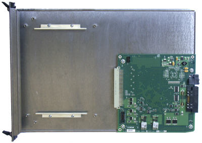
The XG12 adapter module allows Ixia Standard Form Factor (SFF) load modules to be adapted into the XG12 chassis. Figure 6-3 shows an SFF adapter module.

Figure 6-3. SFF Adapter

A SFF load module is inserted into the front of the adapter and connects to the pins in the rear of the adapter. The entire assembly can then be inserted into any XG12 chassis slot.

Once an adapter module is installed in a chassis, SFF load modules can be hot-swapped without removing the SFF load module from the chassis.

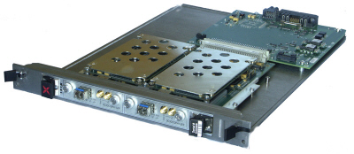
Figure 6-4 shows an SFF Adapter module with a legacy ATM card.

Figure 6-4. SFF Adapter with ATM Module

Table 6-7 identifies the modules that can be used with the SFF Adapter.

Cooling Fan Speed Control

The XG12 chassis automatically monitors and measures the temperature of installed load modules. The XG12 automatically adjusts the fan speed to maintain proper cooling.

Power outage recovery and Automatic booting scenario

The BIOS on the XG12 is set to Power On after a power failure.

The XG12 chassis will start up, boot Windows 7 and automatically login to the Ixia user account. Anything that is in the Startup folder will also launch..

Rack Mount Cautions

Caution: If this unit is installed in a network equipment rack, please observe the following precautions.

    1. Elevated Operating Ambient Temperature: If installed in a closed or multi-unit rack assembly, the operating ambient temperature of the rack environment may be greater than room ambient temperature. Therefore, consider installing the equipment in an environment that is compatible with the maximum allowable ambient temperature specified for the chassis (40° C).
    2. Reduced Air Flow: Install the equipment in a rack so that the amount of air flow required for safe operation of the equipment is not reduced. Do not block the back or the front of the chassis, and leave approximately 12 inches of space, 24 inches preferred, for the back of the unit for proper ventilation. The air flow clearance should be 12 inches on the front.
    3. Mechanical Loading: Mount the chassis so that is it level in the rack and that a hazardous condition is not caused. Please install all six mounting bolts.
    4. Circuit Overloading: Consider the connection of the equipment to the supply circuit and the effect that overloading of the circuits might have on overcurrent protection and supply wiring. Pay attention to equipment nameplate ratings when addressing this concern.
    5. Reliable Earthing: Maintain reliable earthing (grounding) of rack-mounted equipment. Chassis frame should be screwed down to racks to ensure proper grounding path. In Addition, Pay special attention to supply connections other than direct connections to the branch circuit (such as use of power strips).
    6. Replacement of the power supply cord must of the same type cord and plug configuration that was shipped with the unit.

PreviousNextIndex

Did this document 
answer your question?

If not, let us know!


Voice: (818) 871-1800
Fax: (818) 871-1805
info@ixiacom.com