section in PDF
manual in PDF


|
|
|
| |
| Get this section in PDF |
Get entire manual in PDF |
|
Chapter 25: IXIA 10 Gigabit Ethernet Load Modules
This chapter provides details about 10 Gigabit Ethernet (10GE) family of load modules—the specifications and features.
The 10 Gigabit Ethernet (10GE) family of load modules implements five of the seven IEEE 8.2.3ae compliant interfaces that run at 10Gbit/second. Cards are available which offer the following interfaces:
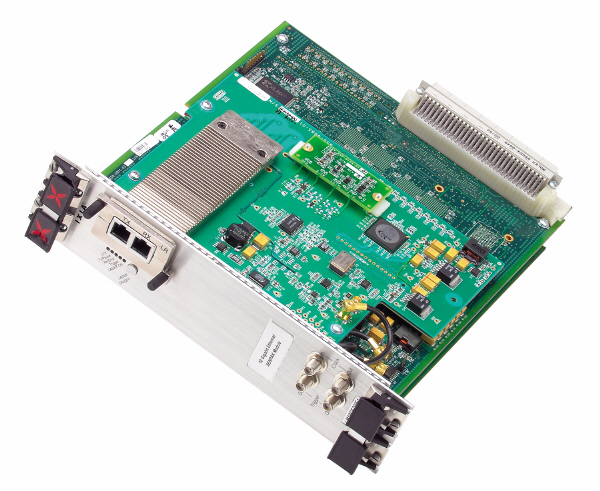
Figure 25-1 on page 25-2 shows an LM10GEXENPAK module.
Figure 25-1. LM10GEXENPAK
In addition, two families of multimode card are available which offers combined 10GE LAN/WAN, OC192 POS, BERT, and FEC functionality. The features available for these load modules are described in Chapter 26, IXIA 10GE LAN/WAN and OC 192 POS Load Modules.
The full details for these families may be found at:
LSM 10GE Family
The Ixia 10 Gigabit Ethernet LAN Service Module (LSM) offers unprecedented scalability, performance, and service testing flexibility. The Ixia 10GE LSM is Ixia's third-generation 10 Gigabit Ethernet solution. It is the industry's first six-port solution, and it offers a broad portfolio of edge/core testing solutions for the most demanding test environments including performance, scalability, and conformance testing of Layer 2-3, Routing Protocols, and high performance Layer 4-7 testing. It supports IPv4 and IPv6 wire-speed traffic generation, advanced analysis and IPv4 and IPv6 routing protocol emulation.
The Ixia 10GE LSM supports a comprehensive portfolio of service testing solutions for the next-generation service provider networks including Metro Ethernet E-LAN and E-LINE services; and MPLS VPNs such as Layer 2 VPNs, Layer 3 RFC 2547 VPNs, and VPLS.
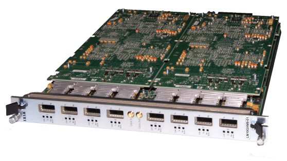
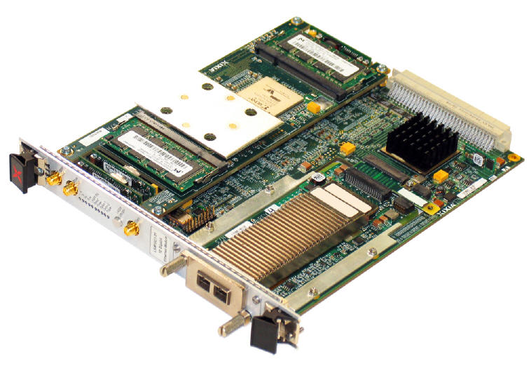
Figure 25-2. LSM10GXM8-01 NGY Load Module
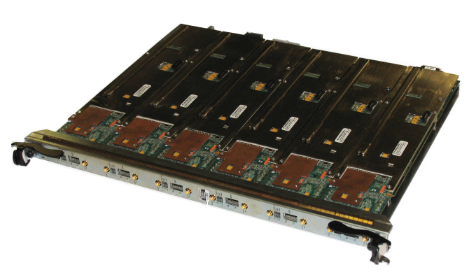
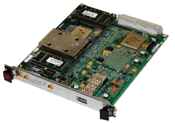
Figure 25-3. LSM10GXL6-01 Load Module
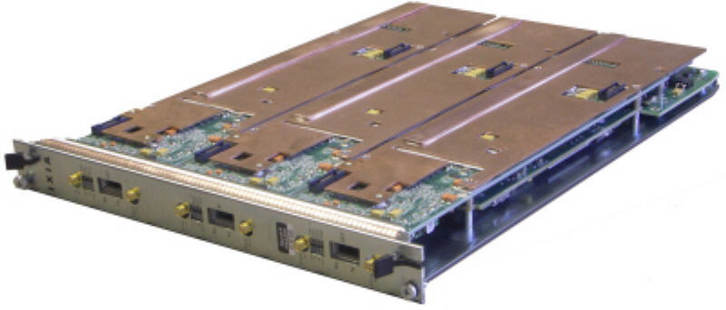
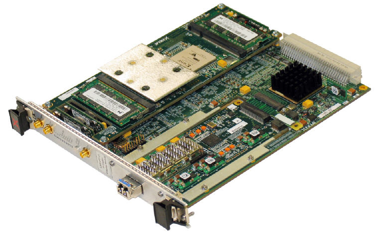
Figure 25-4. LSM10GXM3-01 Load Module
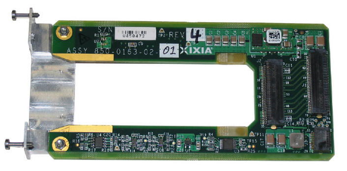
Figure 25-5. LSM10GL1-01(XENPAK Carrier Card)
Figure 25-6. LSM10GMS-01(MACsec Carrier Card)
Figure 25-7. LSM10GL1-01 (XFP Carrier Card)
Part Numbers
The LSM family part numbers are shown in Table 25-1.
.
LSM10GXMR3-012
500MHz (GL1)
128MB (GL1)
Frequency-Mode
(5×C to 35×C)
(5×C to 35×C)
min-max
min-max3
min-max
Fast: 1525fps
Fast: 1525fps
Fast: 1525fps
Fast: 1525fps
32K (reduced)
32K (GXMR3)
512K entries GL1:
8K entries
512K entriesGXMR3-01:
8K entries
256 entries GL1:
16 entries
256 entriesGXMR3-01:
16 entries
1Applications are not supported on LSM10GL1-01 (no Layer 4-5 support).
2The LSM10GMXR3-01 only supports IxNetwork, IxAutomate, and IxExplorer.
3Packet gap size also depends on the stream mode selected—Fixed or Average.
4Streams are divided up into two categories: 224 slow speed streams and 32 fast streams.
5Cancel Intrinsic Latency feature measures and/or removes the latency induced by the test equipment (not the DUT). See Intrinsic Latency Adjustment on page 25-21.
.
XM12 High Performance
XM2 Desktop
64 bytes—minimum frame size at line rate
min-max
min-max
min-max
Fast: 1525fps
Fast: 1525fps
Fast: 1525fps
Slow: 480
Slow: 480
Slow: 480
Slow: 224
Slow: 224
Slow: 224
(counter size: 64 bits)
- LAN mode: -105 to +105 ppm3
- WAN mode: -30 to +30 ppm
1XM12 High Performance chassis (941-0009) is required for 80 or more ports of 10 GbE NGY XFP or SFP+ 8-port, load modules to be installed in a single chassis. A field replaceable power supply upgrade kit (943-0005) is available for the XM12 chassis (941-0002) to convert it to the high-performance version. Up to ten 8-port NGY 10GBASE-T full performance load modules are supported in an XM12 High Performance chassis, and up to eight 8-port NGY 10GBASE-T full performance load modules are supported in a standard XM12 chassis). The XM2 chassis (941-0003) supports up to twelve ports of 10GBASE-T full performance load modules.
2The LSM10GXM8XP, LSM10GXM8S, and LSM10GXM8GBT use a high performance 800MHz processor with additional layer 2 cache.
3For 10GBASE-T interfaces on NGY the ppm does change the data rate, but does not change the bit period due to phy chip limitations.
4When an NGY load module is installed in an XM12 or XM2 chassis, the maximum operating temperature of the chassis is 35°C (ambient air).
Port LEDs
Each 10GB port incorporates a set of LEDs, as described in the following figure.
Clock In/Out
The load module provides coaxial connectors for clock input and clock output to allow the DUT to phase-lock with the interface. When running off an external clock, the clock input signal must meet the requirements listed in the following figure to ensure proper performance of the load module.
The clock in/out electrical interface parameters are also defined in the following figure.
The load module contains a phase-locked loop (PLL) that reduces the jitter of the input clock, either from the internal or external clock source. The bandwidth of the PLL is approximately 1 kHz.
Trigger Out Values
The signals and LEDs available on the trigger out pins for these cards are described in the following table.
Removable Carrier Cards
The 10GE10G1-01 and the LSM10GL1-01 load modules have removable carrier cards available for use:
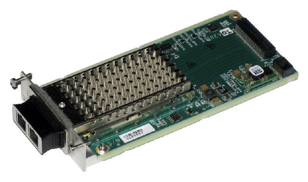
- The XENPAK-ADAP-01 carrier card for XENPAK transceivers, shown in Figure 25-8 on page 25-16.
- The XFP-ADAP-01 LAN only carrier card for XFP transceivers (not shown).
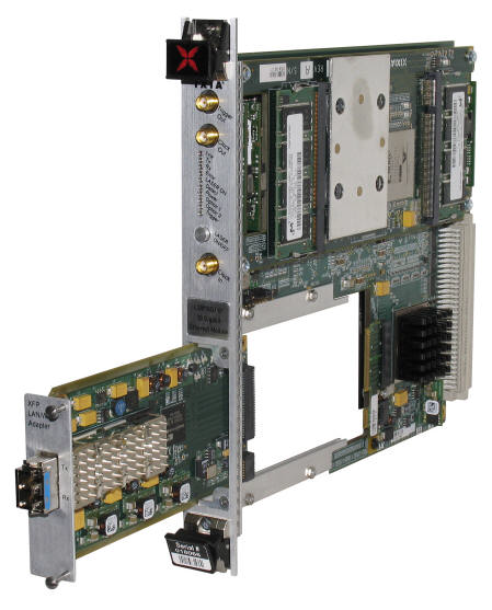
- The XFP-ADAP-02 LAN/WAN carrier card for XFP transceivers (shown being inserted into the LSM load module in Figure 25-10 on page 25-18.
- X2 carrier card for X2 Transceiver (shown with transceiver installed in Figure 25-9 on page 25-17).
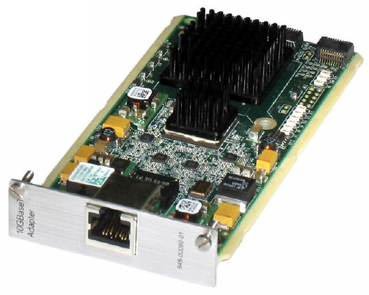
- 10GBase-T-ADAP-01 10 Gigabit Ethernet adapter module (shown in Figure 25-11 on page 25-19).
Figure 25-8. XENPAK-ADAP-01 Carrier Card
Figure 25-9. X2 Carrier Card with X2 Transceiver
Figure 25-10. XFP-ADAP-02 Carrier Card
Figure 25-11. 10GBase-T Adapter Module
Carrier Card Installation
To install the carrier card, do the following:
The carrier card can be installed either before or after the load module is connected to the chassis. It is best not to attach the transceiver to the carrier card until the card is installed in the load module. Load modules should be screwed down in the chassis before removing or installing a carrier card, to prevent from accidentally dislodging a load module from the chassis backplane.
XENPAK/XAUI Connectors
The LSM10G1-01 and LSM10GL1-01 load modules have XAUI and XENPAK connectors available. See XAUI Connectors on page 25-28 and XENPAK Connectors on page 25-34 above for more information on XENPAK connectors.
These connectors are only applicable when the XENPAK carrier is being used.
Statistics
Statistics for 10GE LSM cards (except NGY), under various modes of operation may be found in Table B-23 on page B-118. Statistics for NGY load modules may be found in Table B-24 on page B-127.
NGY Fault Handling
IEEE Requirements
IEEE 802.3ae, section 46.3.4 defines how a Reconciliation Sublayer (RS) shall respond to Local and Remote Faults. Response to a Local Fault is to immediately cease sending traffic on the transmit data path (even if doing so truncates a frame) and to send continual Remote Faults. Response to a Remote Fault is to stop sending MAC data (completing any frame that is being transmitted) and to send continual idles.
NGY Operation
NGY load modules have a single statistic for Faults called Link Fault State. This statistic is real-time and indicates the current state of the port's Reconciliation Sublayer (RS) state machine. The possible statistics values are:
Features that force deviation from IEEE spec
Tx Ignores Rx Link Faults
This feature is enabled through the Link Fault Signaling tab of Port Properties. When the feature is enabled, the Fault statistic continues to indicate the RS state of the port; however, the transmit-side response behaves as if no fault was received. That is to say, Remote Faults are not sent as a response to Local Fault and Idles are not forced as a response to Remote Fault, even though Link Fault State indicates the board is in a Fault state.
Transmit Ignores Link Status
This feature is enabled through the Transmit Modes tab of Port Properties. When the feature is enabled, a port is permitted to transmit under conditions that would normally inhibit transmit. For instance, a port that has no link and is not in diagnostic loopback appears in IxExplorer as red color, and is normally not permitted to transmit. Enabling this feature allows transmit. When the feature is enabled, the statistic called Link State indicates `Ignore Link'.
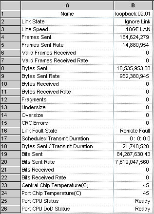
Note that if the port is in Fault, enabling this feature and forcing transmit may result in misleading results. The port shown in the following stat view (Figure 25-12) is ignoring link (see Link State statistic), is in Remote Fault (see Link Fault State statistic), yet appears to be transmitting (see Frames Sent Rate statistic). The reality is that no frames are actually leaving the port because the port is in Remote Fault. This is because the block that maintains the transmit statistics is located before the block that forces idles as a response to Remote Fault.
Figure 25-12.
Statistic View for NGY, Ignore Link Status
Intrinsic Latency Adjustment
This option, when present and enabled, reduces the measured latency by the amount of latency that is induced by the test equipment itself (not the DUT). For a specific transceiver, the system retrieves its pre-determined latency value and subtracts this from the measured overall latency. For an `unknown' transceiver (not previously measured), it calculates and stores the intrinsic latency value.
On the General tab in Port Properties, the Latency Calibration option is only enabled for cards with transceivers that have not been pre-measured for intrinisic latency by Ixia. The Latency Calibration option is grayed-out if any one of the following conditions are present:
The Latency Calibration option is enabled if the transceiver is XENPAK or X2 but no pre-calibrated value is found in the stored list. The Latency Calibration option is also enabled for transceivers that you have previously calibrated, so that the calibration measurement may be repeated (if desired).
Clicking the Latency Calibration option runs a Tcl script that measures intrinsic latency and stores the value in an .xml file. The .xml file contains the values that you have produced and saved. Each value is identified for a specific transceiver (per manufacturer, model, and serial number). You can run the calibrate process repeatedly with the same transceiver (if desired). Each new measurement overwrites the previous one for that transceiver.
Running the calibration measurement puts the port into a special loopback mode to measure intrinsic latency. When done, the port is put back into default normal mode. Any port configuration you have set before calibrating intrinsic latency, is lost as the port reverts to a default configuration.
The Enable check box is grayed out when no value exists in the system for the specific transceiver. If a value exists (in the .xml file) then the Enable check box is available. Select the check box to enable the intrinsic latency adjustment.
After the intrinsic latency adjustment has been done, you may want to refresh the chassis or close and reopen the Port Properties dialog.
10GE LAN Family
Part Numbers
The currently available LAN family part numbers are shown in the following table. Items without a Price List Names entry are no longer available.
Specifications
The limitations of -M, Layer 2/3 and Layer 7 cards are discussed in Ixia Load Modules on page 1-5.
Med: 95fps
Fast: 1525fps
1Streams are divided up into three categories: 144 slow speed streams, 8 medium streams and 8 fast streams.
The LAN-M boards includes all of the features of the LAN board with the following exceptions:
When performing sequence checking, no more than 8192 packet group IDs should be used.
Port LEDs
Each 10GB LAN port incorporates a set of LEDs, as described in the Table 25-9.
Trigger Out Values
The signals and LEDs available on the trigger out pins for these cards are described in the following table.
Optical Specifications
The optical characteristics for the 10GE LAN cards is described in Table 25-11.
Statistics
Statistics for 10GB cards, under various modes of operation may be found in Table B-21 on page B-104 and Table B-22 on page B-111.
XAUI Family
Part Numbers
The XAUI family part numbers are shown in the following table.
Specifications
The limitations of -M, Layer 2/3 and Layer 7 cards are discussed in Ixia Load Modules on page 1-5.
Med: 95fps
Fast: 1525fps
1Streams are divided up into three categories: 144 slow speed streams, 8 medium streams and 8 fast streams.
XAUI accessories are discussed in Appendix A, XAUI Connector Specifications.
Port LEDs
Each 10GB XAUI port incorporates a set of LEDs, as described in the following table.
Trigger Out Values
The signals and LEDs available on the trigger out pins for these cards are described in the following figure.
Clock In/Out
The XAUI load module provides SMA coaxial connectors for clock input and clock output to allow the DUT to phase-lock with the XAUI interface. When running off an external clock, the clock input signal must meet the requirements listed in Table 25-16 to ensure proper performance of the load module.
The clock in/out electrical interface parameters are defined in Table 25-17.
The load module contains a phase-locked loop (PLL) that reduces the jitter of the input clock, either from the internal or external clock source. The bandwidth of the PLL is approximately 1kHz.
XAUI Connectors
The following connectors and adapters are available for the XAUI Load Modules and are discussed in Appendix A, XAUI Connector Specifications.
- Standard Connector Specifications: the signals carried on the Load Module's XAUI connector.
- Front Panel Loopback Connector: a connector used to loopback XAUI signals at the external connector.
- Standard Cable Specification: the CAB10GE500S1 (20 inch) and CAB10GE500S2 (40 inch) cables.
- SMA Break-Out Box: the BOB10GE500 SMA break-out box.
MDIO
A Management Data Input/Output (MDIO) interface is provided to you. The Ixia Load Module acts as the Station Management entity (STA), and can control one or more MDIO Manageable Devices (MMD) in the users system. Multiple MMDs can be attached to the interface. You can set/read the MDIO control/status registers inside a MMD through a graphical user interface.
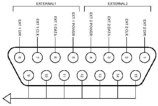
The connector used for the MDIO interface is a 15-pin female D-sub and provides with the ability to add up to two external Mii interfaces compliant to either 802.3 clause 22 or 802.3ae clause 45. The connector pin assignments, Mii Interface, signal names, and functional descriptions are listed in Table 25-18.
Figure 25-13. MDC/MDIO D-sub Connector Pin
Assignments
The MDIO/MDC interface has a clock line (MDC) and bi-directional data line (MDIO) as defined in IEEE 802.3ae. In addition to these, a +5Vdc supply, and data direction control line (DIR) are provided to make interfacing easier for you. The +5Vdc output is intended to power buffers and/or optocouplers at the user-end of the cable. This supply can be turned ON or OFF under software control through the GUI.
The +5Vdc supply is OFF when the chassis is initially powered-up, or following a reset.
For more information on XAUI connectors, see Appendix A, XAUI Connector Specifications.
Statistics
Statistics for 10GB cards, under various modes of operation may be found in Table B-21 on page B-104 and Table B-22 on page B-111.
XENPAK Family
The LM10GE700P3 family is referred to as the XENPAK load modules. Each card accepts a XENPAK transceiver, or with an appropriate carrier card accepts an XPAK or X2 transceiver. Five variants are available, which feature Ethernet and/or BERT modes and full or manufacturing mode.
Part Numbers
The XENPAK family part numbers are shown in Table 25-19.
Specifications
The limitations of -M, Layer 2/3 and Layer 7 cards are discussed in Ixia Load Modules on page 1-5.
Frequency-Mode
min-max
min-max
Med: 95fps
Fast: 1525fps
1Streams are divided up into three categories: 144 slow speed streams, 8 medium streams and 8 fast streams.
The -M load modules includes all of the features of the non-M board with the following exceptions:
When performing sequence checking, no more than 8192 packet group IDs should be used.
Port LEDs
Each 10GB port incorporates a set of LEDs, as described in the following tables.
Trigger Out Values
Trigger out values depend on the particular board type.
XENPAK Load Modules
The signals and LEDs available on the trigger out pins for these cards are described in Table 25-22.
Clock In/Out
The load module provides SMA coaxial connectors for clock input and clock output to allow the DUT to phase-lock with the interface. When running off an external clock, the clock input signal must meet the requirements listed in Table 25-23 to ensure proper performance of the load module.
The clock in/out electrical interface parameters are defined in Table 25-24.
The load module contains a phase-locked loop (PLL) that reduces the jitter of the input clock, either from the internal or external clock source. The bandwidth of the PLL is approximately 1kHz.
XENPAK Connectors
Power Sequencing Specification
The Xenpak 2.1 MSA does not specify any particular power sequencing for the various Xenpak power supply rails (3.3V, 5V, and APS).
When Xenpak Power is enabled, power sequencing is as follows:
Reset
Hardware asserts a Reset by bringing Xenpak connector pin 10 low whenever either of the following conditions is true:
The hardware continues to assert Reset until both of these items are false. Once Xenpak Power is asserted, or if a Xenpak is hot-plugged, the system waits 5 seconds for Xenpak initialization (per MSA 2.1). Reset is then de-asserted, and the system waits an additional 500 ms for any vendor-based reset management to complete initialization. After this final 500 ms delay, the load module assumes the Xenpak module is ready for MII access or to transmit and receive.
XAUI Fujitsu to XENPAK Adapter
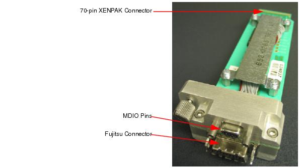
The XAUI Fujitsu to XENPAK Adapter (P/N FXN10GE500) is shown in Figure 25-14.
Figure 25-14. XAUI Fujitsu to XENPAK Adapter
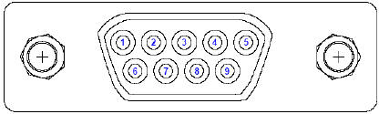
The MDIO pins are pictured and described in Figure 25-15 and Table 25-25.
Figure 25-15. MDIO Pins for XAUI Fujitsu to XENPAK Adapter
This MDIO pinout is the same for the CX4 to XENPAK adapter (P/N CX410GE500).
For more information on XAUI connectors, see Appendix A, XAUI Connector Specifications.
CX4 to XENPAK Adapter
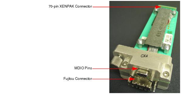
The CX4 to XENPAK Adapter (P/N CX410GE500) is shown in Figure 25-16.
Figure 25-16. CX4 to XENPAK Adapter
The MDIO pins are pictured and described in Figure 25-15 and Table 25-25.
For more information on XAUI connectors, see Appendix A, XAUI Connector Specifications.
Statistics
Statistics for 10GB cards, under various modes of operation may be found in Table B-21 on page B-104 and Table B-22 on page B-111.
|
|
Did this document answer your question?
If not, let us know! |
|